American Lighting K-1063 User Manual
Led 120v dimmable panel, Save these instructions
WARNING: These products may represent a possible shock or fire hazard if improperly installed or attached in
any way. Products should be installed in accordance with these instructions, and with current electrical codes
and/or the current National Electric Code (NEC). For surface mount installation only.
Save these instructions.
Warning: To avoid electric shock, disconnect power prior to installation.
Caution: Injury to persons and damage to the fixture and/or mounting surface may result if the fixture is pulled from the surface.
To reduce the likelihood of such injury or damage, mount on a surface that is mechanically sound. NOTE: Installation requires a set
of two standoffs (one for each suspension mounting bracket, see Figure 2). 3” sets are available for each fixture. Installer can
purchase other standoff hardware - the diameter of the hole in the
suspension mounting bracket is 21/32”.
Use only a mild soap and/or water with soft cloth to clean the fixture. Do not wipe
the fixture with a rough cloth that may scratch the finish or the lens.
If your system has no ground wire, you should consult a qualified
electrician before proceeding with the installation.
Unpack the fixture and inspect the lead wires for any damage. If there is
any damage to the cord, do not install. Use minimum 18AWG solid
copper wires. AC supply should be 120V protected by circuit
breaker or fuse.
Turn off power at source before proceeding!
Input: 120V AC, 60Hz operation only
Surface mount installation using suspension hardware:
1. Determine desired location for LED Panel. Mark the locations of the
two standoff hardware sets on the ceiling. See Figure 1 for required
distances between sets.
2. Attached the two standoff hardware sets to the ceiling with
fasteners that are appropriate for material of the mounting surface.
See Figure 1.
3. Attach the suspension mounting brackets to the back of the fixture
with the screws provided and the holes that are pre-drilled into the
housing for this purpose, making sure the brackets are secure.
There is one suspension mounting bracket on each end.
See Figure 2.
4. Remove wiring compartment cover on back of fixture by sliding
cover toward corner of fixture until retaining tabs are released, then
lifting off. See Figure 3.
RV1311
www.americanlighting.com
Page 1 of 2
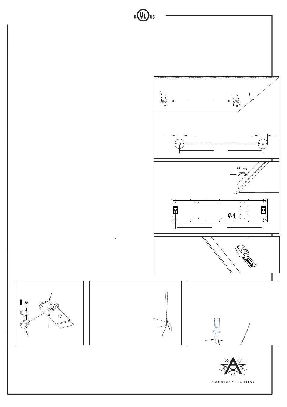
Figure 1
Figure 2
LED 120V Dimmable Panel
Surface Mount Installation Instructions for K-1063 (SKU = PK-1X4-41-S)
Ceiling
3.5"
43.7"
Attach standoff hardware sets to ceiling using appropriate
fasteners and measurements below for proper spacing.
Attach suspension mounting brackets
to back of fixture (one at each corner)
using small screws (included) and
measurements below for proper spacing.
Standoff
hardware
sets
Figure 4
Figure 5
Figure 6
5. Punch out one of the knockouts on the wiring compartment cover
and install a 1/2” standard cable connector/strain relief clamp
(not supplied with fixture, see Figure 4) or other UL approved strain
relief connector onto this knockout.
6. Prepare supply wires by stripping back to 3/8”. See Figure 5.
7. Thread supply wires through wiring compartment cover via strain
relief connector. Do not use any other knockouts for supply power.
8. A mating power connector is supplied with each fixture to connect to
supply wires. Attach mating connector to the Black and White supply
wires. Ground wire does not connect to this connector. See Figure 6.
Standard 1/2” cable connector
Knockout
Wiring
compartment
cover
Green/bare
wire (ground)
White wire
(neutral)
Black wire (hot)
1
2
Prepare supply wires by stripping
back to 3/8”. Pull enough length to
reach through wiring compartment
cover/knockout assembly.
Use minimum 18AWG solid copper supply wires.
Attach mating power connector to supply wires,
making sure that Black matches to ‘1’ and White
matches to ‘2’ as marked on the connector.
White wire
(neutral)
Black wire
(hot)
4.25"
43.7"
Figure 3
Slide wiring compartment
cover toward corner to
release retaining tabs,
then lift to gain access to
wiring compartment.
Note to installer:
It is possible to run the jacketed supply wires (18-3 or better) through one of the standoff
hardware stems. Pull wire from ceiling at one stem location with enough length to feed
through the stem, across the top of the housing and into the wiring compartment (via the
strain relief connector). Use only the knockout(s) in the wiring compartment cover for
connecting power.