American Lighting LVP Series User Manual
Led puck light installation instructions
LED Puck Light Installation Instructions
Installation instructions for LVP Series
WARNING: These products may represent a possible shock or fire hazard if improperly installed or attached
in any way. Products should be installed in accordance with these instructions, current electrical codes
and/or the current National Electric Code (NEC). Disconnect power to the unit prior to installation.
NOTE: There are two power supply delivery systems available for the Dimmable LED Puck Lights:
I). a 15-volt, 9-watt plug-in LED driver and a 3-port power connection hub with attached dimmer and
II). a 15-volt, 15-watt plug-in LED driver and a 6-port power connection hub with attached dimmer.
The maximum number of pucks that can be powered from one power supply is limited by the number of
ports in a power connection system and the capacity of the power supply itself.
CAUTION: Do not alter the power supply or dimmer. Do not cut off or remove any power connection
jacks. This will void the warranty, and likely cause the product to fail. The LED Puck Light is designed for
plug-in use only.
WARNING! Risk of fire and electric shock. Make sure
to shut off power at source before beginning
installation or servicing of any kind. Please read
these instructions before attempting to assemble,
operate or install the product. For indoor use only.
SURFACE MOUNTING:
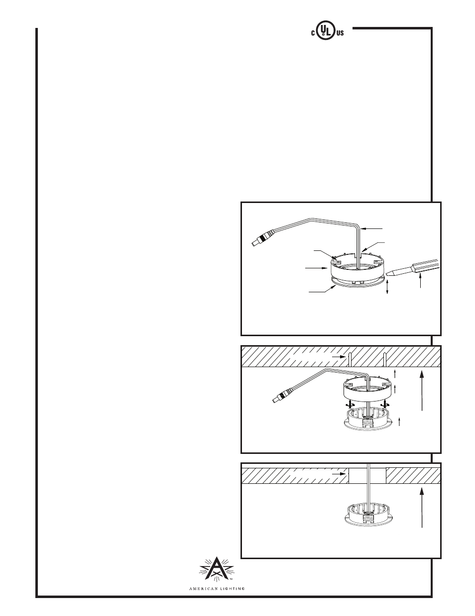
1. Remove the surface ring by holding the surface ring
with your fingers and pushing the puck out from the
back using your thumbs on the back of the puck light.
Alternatively, you can locate the line where the surface
ring and LED Puck Light meet and carefully use a flat
screwdriver to separate the two parts. See Figure 1.
2. Determine desired locations for each puck and mark
the locations of the mounting holes on the mounting
surface, using the surface ring as a template.
Note: Each puck light has a five foot lead wire which
needs to be routed to the power connection hub.
Be sure to locate the puck lights and power hub such
that each puck can reach a port.
3. Before surface mounting the puck light’s surface
ring, route the lead wire through the installation
notch. Drill 1/8” pilot holes into the mounting
surface where marked, and secure surface ring
to mounting surface using mounting screws
included. See Figure 2.
4. Gently push the puck light into the surface ring until
it is fully seated, making sure that the lead wire is not
pinched or crimped in any way. See Figure 2.
5. See POWER CONNECTION on reverse for next steps.
Figure 1
screwdriver
installation notch
lead wire
LED Puck Light
surface ring
mounting holes
Before surface mounting the surface ring, route the lead
wire through the installation notch.
Figure 2
mounting
surface
pilot holes
RV-1230
www.americanlighting.com
Surface Mounting Illustration
Figure 3
mounting
surface
Recess Mounting Illustration
2-5/8” hole