Led linear wall washer – American Lighting LW36X1-RGB User Manual
Page 2
LED Linear Wall Washer
Safety instructions for LW12X1-RGB, LW24X1-RGB and LW36X1-RGB
RV-1328
Page 2 of 4
INSTALLATION CONSIDERATIONS
The maximum number of fixtures that can be controlled by the LW36-CON controller is thirty.
For any project that requires more than thirty fixtures, please consult factory.
1. Determine the number of fixtures to be used. Consider the locations of all fixtures and of the controller.
2. Create a lighting plan that itemizes where each unit is located and routing plan for signal cables.
Provide a grounded receptacle for within 5’ of each fixtures location. See Figure 2 and “Fixture Installation”.
If using outdoors, outlet(s) must also be GFCI and weatherproof.
3. Locate the controller within 175 feet of the last fixture in a series. Note: The controller is usually installed
after the fixtures are in place and will require its own 120V AC outlet within 7’ of its location. See Figure 2.
4. Route signal cables per lighting plan established above.
FIXTURE INSTALLATION
1. Be sure to record the fixtures’ IDs on the lighting plan. Label the fixtures with their assigned locations by
attaching a weatherproof label to each unit.
2. Set the fixtures’ IDs. Note: If you want all the fixtures to be synchronized, give them all the same ID. To
change/set an ID, simply press the contact buttoms on the underside of the fixture next to the LED screen
(one will advance the IDs, the other will lower ID numbers). The fixture’s ID will be held in memory even
when unplugged or otherwise powered off.
3. Consider what mounting hardware will be used. The mounting surface will dictate the
type of fastener. The base has through-holes for mounting. See Figure 3 for details.
4. Mount the fixture securely to the mounting surface using appropriate fasteners.
*Specialized DMX software will allow multiple IDs for advanced effect lighting. All fixtures
connected to the LW36-CON controller will automatically syncronize. When using DMX 512
software, refer to that manufacture’s instructions.
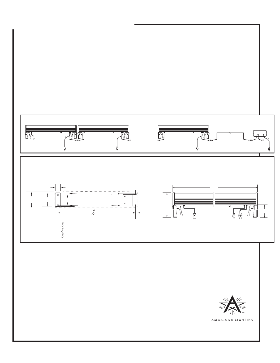
Figure 2
Figure 3
CONTINUED ON PAGE 3
CONTINUED FROM PAGE 1
Shown below: signal cables interconnecting fixtures. Provide grounded outlet for each unit and also for controller.
L
5”
2-1/2”
L = 15-3/4” for LW12X1 Series
L = 31-1/2” for LW24X1 Series
L = 47-1/4” for LW26X1 Series
2-1/16”
2-3/16”
1-1/2” between centers
1-1/2”
3/4”
.30”
3/8”
Top View
Looking toward mounting surface through
housing body showing holes in mounting brackets
= 13-13/16” for LW12X1 Series
= 29-7/16” for LW24X1 Series
= 48-1/8” for LW26X1 Series
.22”
.30”
.22”
Side View
www.americanlighting.com
LW36-CON