3 configuration steps, Set up the device, Wla-9000ap’s factory default value ip – AirLive WLA-9000AP PCBA User Manual
Page 10: 2 back side introduction
2. Install the WLA-9000AP
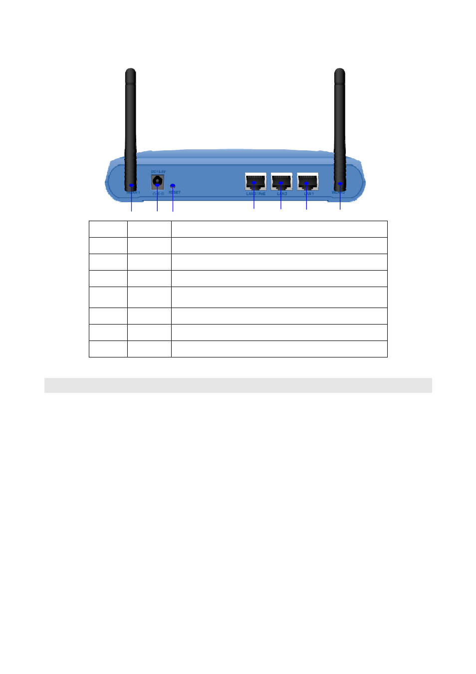
2.2.2 Back side introduction
Port #
Display
4
5
6
7
2
1
3
Description
Detachable antenna with R-SMA connector. 2 indoor 2dBi antennas
are delivered.
1
WLAN1
2
Power
Adaptor
5.5V 2.5A power supply adaptor delivered with product.
3
RESET
Reset button for rebooting and reset device as default facory value.
LAN port 3 and PoE port. It can be plug 802.3af compliant PoE as
power and data supply.
4
LAN 3/PoE
5
LAN 2
LAN port 2
6
LAN 1
LAN port 1
7
WLAN2
Detachable antenna with R-SMA connector.
2.3 Configuration steps
This section describes configuration required for the WLA-9000AP before it can work
properly in your network.
Set up the device
The WLA-9000AP can be managed remotely by a PC through either the wired or wireless
network. To do this, the WLA-9000AP must first be assigned an IP address, which can be
done using one of the following 2 methods.
WLA-9000AP’s Factory default value IP
The default IP address of the LAN interface of an WLA-9000AP is a private IP address of
192.168.1.1, and a network mask of 255.255.255.0. This means IP addresses of other
devices on the LAN should be in the range of 192.168.1.2 to 192.168.1.254.
This IP address can be modified to either a different address in this same subnet or to an
address in a different subnet, depending on the existing network settings (if there is any) or
user’s preferences.
5
AirLive WLA-9000AP User’s Manual