7 interfaces, 1 interface configuration, 2 24v dc power supply – ADS-TEC OPC6115/6315 User Manual
Page 24
OPC6115/6315
23
© ads‐tec GmbH • Raiffeisenstr.14 • 70771 Leinfelden‐Echterdingen
7 Interfaces
7.1 Interface configuration
Interface
IRQ
Adress
COM1
4
3F8h
COM2
3
2F8h
On the left side of the case, the interfaces are arranged. All interfaces are labeled. The IEC connector or through
terminal for the power supply is located on the right side of the control system.
Note:
Under the embedded operating system Windows CE.net the communication
interfaces (COM, USB, etc.) have to be explicitly be enabled and drivers need to be
installed
Pos: 26 /Datentechnik/Schnittstellen/Spannungsversorgung/Spannungsversorgung für VMT60xx-Serie @ 2\mod_1260450284020_6.doc @ 6853 @
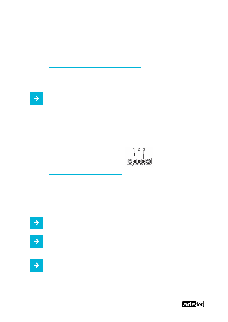
7.2 24V DC Power Supply
The supply voltage is provided via a lead‐through terminal including a screw connection (Phoenix Contact
COMBICON MC 1,5/4‐STF3.81). (The figure shows the socket inside the device).
Pin‐Number
Signal‐Name
1
24V DC
2
PE
3
0V DC
Technical Data of the input
•Input:
Max. 130 Watt
•Input current:
19..30 VDC
•current consumption:
8,5A (24 VDC)
•Max. Input current:
18A
Note:
The power supply can be protected with a slow‐blow fuse of up to 4A.
Note:
The typical power consumption of this device is indicated in the "Technical details"
chapter.
Note:
If the case is connected with earth potential at the provided PE contact (e.g. by connecting
the PE contact with the device plug), the electrical insulation is no longer given. This also
applies if the device is installed by using a metal retainer clip.
If you want to have the device electrically insulated from the power supply, you
have to use a method of installation that ensures appropriate insulation.