Warning, 3 chipper blades (con't) – Echo 76824 Owners Manual v.1 User Manual
Page 20
PN 18280-00 R121505
18
SERVICE & MAINTENANCE
BEFORE INSPECTING OR SERVICING ANY PART OF THIS MACHINE, SHUT OFF POWER SOURCE,
DISENGAGE THE HYDRAULICS AND MAKE SURE ALL MOVING PARTS HAVE COME TO A COMPLETE STOP.
WARNING
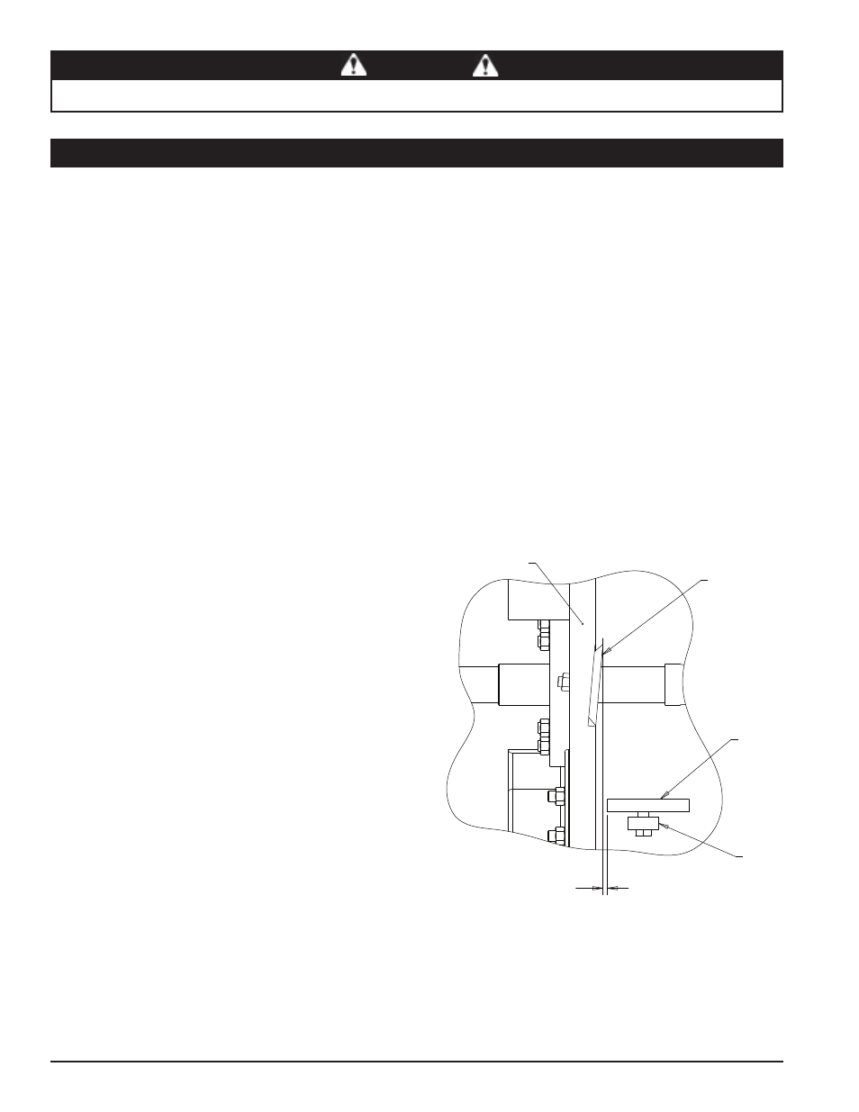
5.3.4 SETTING CHIPPER BLADE CLEARANCE
The chipping blades should clear the chipper block located directly
under the chipper chute by 1/16 inch (Figure 5.4). To adjust the
blade clearance, proceed as follows:
Remove the two 3/8" bolts securing the access cover to the
main frame. Tilt access cover over to allow access to anvil
Loosen the three 1/2 inch bolts that hold the chipper anvil
to the frame.
Measure the amount of clearance between chipping blades
and chipping anvil from inside of housing. Adjust inward or
outward to desired measurement.
Check clearance on all the blades.
Tighten bolts on chipping anvil to 75 Ft-lb and resume op-
eration.
If chipping anvil edge is damaged or worn unevenly, remove
the three bolts holding the anvil and use one of the other
three edges. Adjust for correct measurement.
1.
2.
3.
4.
5.
6.
5.3.3 INSTALLING THE BLADES
Install the disk lock (Section 5.2). The disk is now restrained
for installing the blades.
Place a blade on the disk and attach with two hex head
bolts and nuts. Torque to 120 Ft-lbs. Repeat for remaining
blades.
Lower the access cover and secure to the chipper housing
using two 3/8" retaining bolts.
1.
2.
3.
5.3 CHIPPER BLADES (CON'T)
Figure 5.4 - Chipper Blade/Anvil Clearance
ANVIL
CHIPPER
BLADE
ROTOR
ANVIL
SPACER
1/16" - 1/8"