Warning 5.7 drive belts – Echo 76824 Owners Manual v.2 User Manual
Page 27
PN 18280-00 R041306
25
SERVICE & MAINTENANCE
BEFORE INSPECTING OR SERvICING ANY PART OF ThIS MAChINE, ShuT OFF POWER SOuRCE,
DISENGAGE ThE hYDRAuLICS, OPEN ShIELD AND MAkE SuRE ALL MOvING PARTS hAvE COME TO A COMPLETE STOP.
WARNINg
5.7 DRIvE bELTs
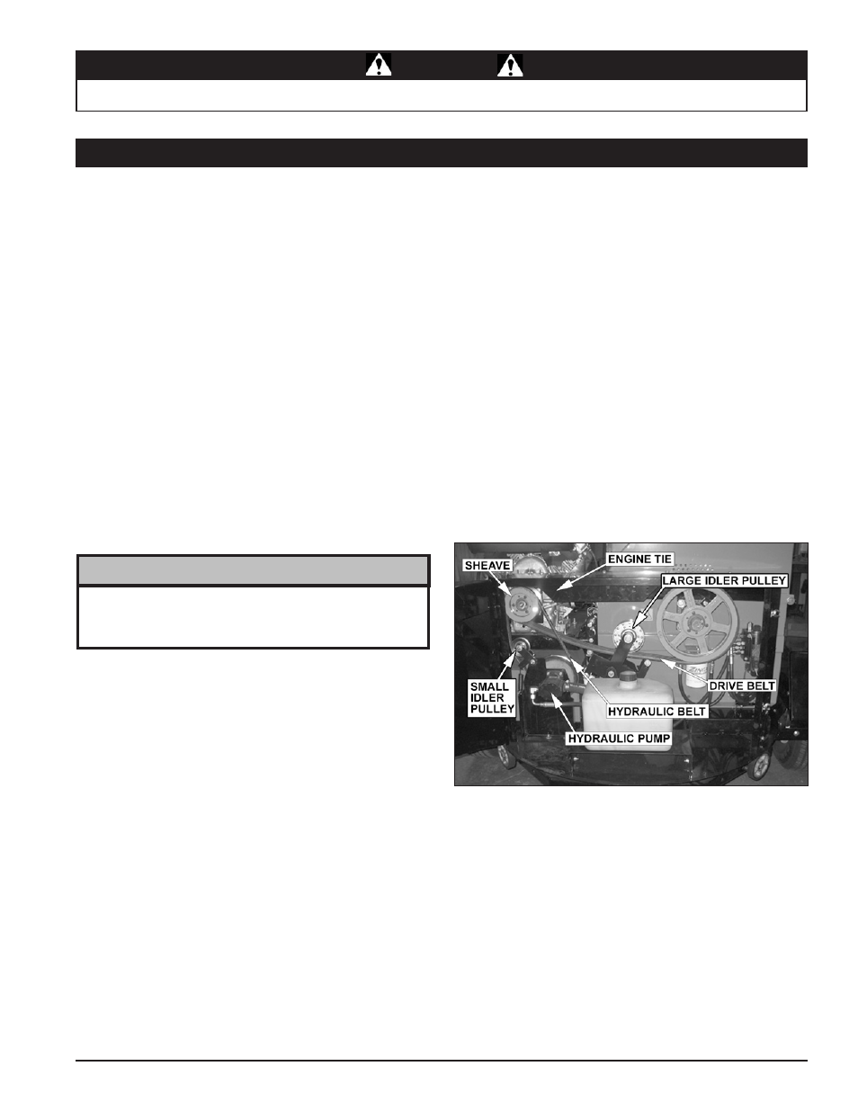
Figure 5.6 - Drive Belt
5.7.1 REpLAcINg DIsk DRIvE bELT
Check the condition of the drive belt annually or after every 25
hours of operation, whichever comes first. If the belt is cracked,
frayed, worn or stretched, replace it. Replace belt with original
banded type belt only. Do not use single type belts.
Lift engagement handle to disengage drive belt.
Loosen bolt on engine tie. DO NOT REMOvE.
Loosen the bolts securing the belt kicker to the engine (lo-
cated above the small sheave). DO NOT REMOvE.
Assure the belt tensioning bolts on the engine mount plate
are tight against the engine mount.
Turn each of the two bolts eight revolutions counterclock-
wise.
Loosen the four engine mount bolts and slide engine towards
chipper housing.
Remove the large idler pulley.
using a wrench, pull the small idler pulley away from the
hydraulic belt to release the tension.
Remove the hydraulic drive belt from the drive pulley on
the engine.
Remove the old disk drive belt and install new disk drive belt
on engine and large pulley.
Install large idler pulley
Lower engagement handle to engage drive belt
Alternately turn each of the belt tension bolts clockwise an
equal number of turns until the belt deflection at the center
of the belt is 7/16” when a 20 lb load is placed against the
belt (Figure 5.5).
Check pulley alignment using a straight edge and adjust the
appropriate belt tension screw if required.
1.
2.
3.
4.
5.
6.
7.
8.
9.
10.
11.
12.
13.
14.
If belt does not easily install, turn the two belt tension bolts
counterclockwise an equal number of turns and slide engine
closer to chipper until belt can be installed.
NoTE
Tighten the four engine mount bolts to the appropriate
torque.
Tighten the bolts securing the belt kickers to the engine.
There should be .028” gap between the drive belt and the
kickers when the belt is engaged.
Tighten the engine tie bolt
using a wrench, pull the small idler pulley towards the center
of the chipper
Install the hydraulic drive belt on the hydraulic pump (on out-
side of idler pulley) and on engine drive pulley (Figure 5.6).
Release idler to apply tension on hydraulic pump drive
belt.
Lift the engagement handle, start engine and lower engage-
ment handle to test units. Adjust pulleys and belt tension as
needed.
15.
16.
17.
18.
19.
20.
21.