Warning, 3 chipper blades (con't), 2 sharpening the blades – Echo 76824 Owners Manual v.2 User Manual
Page 25: 4 setting chipper blade clearance, 3 installing the blades
PN 18280-00 R041306
23
SERVICE & MAINTENANCE
BEFORE INSPECTING OR SERvICING ANY PART OF ThIS MAChINE, ShuT OFF POWER SOuRCE,
DISENGAGE ThE hYDRAuLICS, OPEN ShIELD AND MAkE SuRE ALL MOvING PARTS hAvE COME TO A COMPLETE STOP.
WARNINg
5.3.2 shARpENINg ThE bLADEs
Never sharpen or grind the mounting surfaces of the blades.
This will cause the edge to roll and the blade will be damaged,
resulting in poor chipping performance.
Regrind the angled edge of the chipping blades to 45 degrees
(Figure 5.3).
The blades can be ground on a bench grinder or by a pro-
fessional.
Make sure some type of fixture is used to correctly hold the
blade at the proper angle.
Be careful when grinding so that the blade does not become
overheated and change color. This will remove the heat-
treated properties.
use short grinding times and cool with water or some type
of liquid coolant.
Remove an equal amount off each blade to maintain disk
balance.
Small imperfections such as nicks and burrs on the flat side
of the blade will not affect the chipping performance of the
machine.
For blades that have been repeatedly sharpened, ensure
that the sharpened surface extends past the chipping slot
opening. If it does not extend past the opening, the blades
should be replaced.
1.
2.
3.
4.
5.
6.
7.
8.
9.
Figure 5.3 - Chipper Blade Surfaces
MOUNTING SURFACE
DO NOT GRIND
MOUNTING SURFACE
DO NOT GRIND
SHARPENED
SURFACE
SHARPENED
SURFACE
45˚
.38
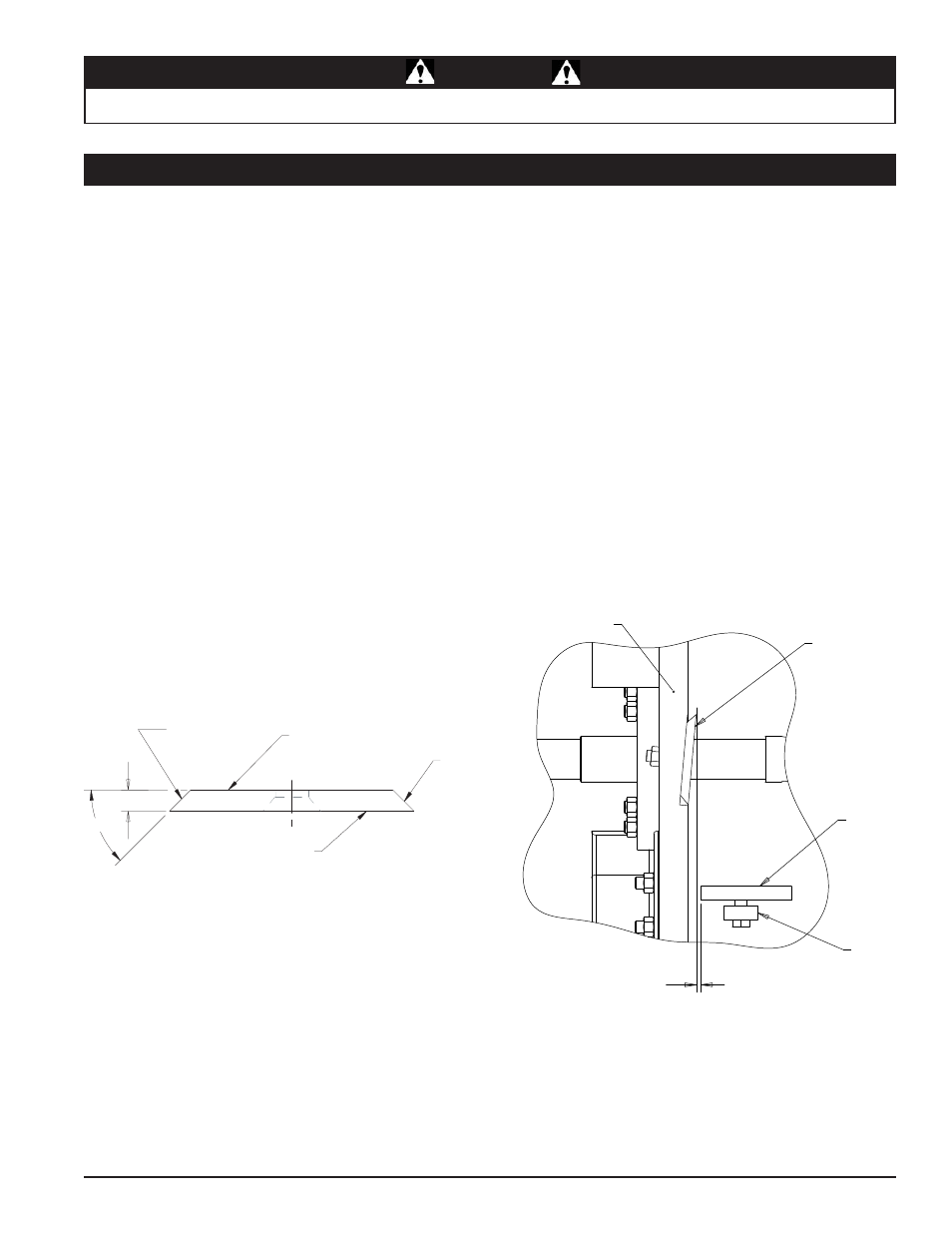
5.3.4 sETTINg chIppER bLADE cLEARANcE
The chipping blades should clear the chipper block located di-
rectly under the chipper chute by 1/16 to 1/8 inch (Figure 5.4).
To adjust the blade clearance, proceed as follows:
Remove the two 3/8" bolts securing the access cover to the
main frame. Tilt access cover over to allow access to anvil
Loosen the three 1/2 inch bolts that hold the chipper anvil
to the frame.
Measure the amount of clearance between chipping blades
and chipping anvil from inside of housing. Adjust inward or
outward to desired measurement.
Check clearance on all the blades.
Tighten bolts on chipping anvil to 75 Ft-lb and resume op-
eration.
If chipping anvil edge is damaged or worn unevenly, remove
the three bolts holding the anvil and use one of the other
three edges. Adjust for correct measurement.
1.
2.
3.
4.
5.
6.
5.3.3 INsTALLINg ThE bLADEs
Install the disk lock (Section 5.2). The disk is now restrained
for installing the blades.
Place a blade on the disk and attach with two hex head
bolts and nuts. Torque to 120 Ft-lbs. Repeat for remaining
blades.
Lower the access cover and secure to the chipper housing
using two 3/8" retaining bolts.
Remove disk lock.
1.
2.
3.
4.
5.3 chIppER bLADEs (coN'T)
Figure 5.4 - Chipper Blade/Anvil Clearance
ANVIL
CHIPPER
BLADE
ROTOR
ANVIL
SPACER
1/16" - 1/8"