7 chipper feed controller, 8 feed roller control bar – Echo 76824 Owners Manual v.2 User Manual
Page 20
PN 18280-00 R041306
18
OPERATION
4.7 chIppER fEED coNTRoLLER
The chipper is equipped with a pre-programmed feed controller.
The controller is located on the chipper housing above the chip-
per chute. The controller serves a variety of functions includ-
ing monitoring chipper disk RPM, controlling the feed roller, and
providing routine maintenance alerts. The control bar located on
the feed chute will control the feed roller.
The controller functions are further detailed below:
The controller operates the feed roller. The controller moni-
tors the RPMs of the chipper disk and won't operate until
the engine is at full RPM. If the chipper disk drops below
the normal operating RPM, the feed roller stops. When the
chipper disk returns to the normal operating RPM, the feed
roller will reengage.
The controller also has a “try again” feature. The controller
monitors the hydraulic pressure of the feed roller. If it senses
the level is too high (the feed roller becomes obstructed) the
controller will reverse the feed roller , removing the material
trying to be chipped. The controller will then engage the roller
into the forward position and try to feed the material again. If
this cycle continues, remove the obstruction manually. Trim
or reposition material if necessary.
1.
2.
The feed controller is programmed to display the following
text messages:
15 hour Service Code: "Change/Service blades".
100 hour Service Code: "Change engine oil".
Normal Operating RPM: "Feed control system
available".
high Pressure: "Try again feature activiated".
Feed Roller Stop Switch: "Forward feed stopped".
- Domestic Models: Disk RPM too low.
- S & F Models: Disk RPM too Low or Safety
Bar Activated.
SAFETY BAR: S & F models only. If safety bar has been
activated the red LED will light up. Push the reset/override
button to resume forward feed (Figure 4.3).
To overcome false trips of the safety bar by material
being chipped, the reset/override button may be held in for
5 seconds. To repeat, release button and hold in again.
NOTE: The RPM sensor on the disk must flash or the controller
won’t work. Clearance between the sensor and the bolt must be
between 1/32” and 3/32”.
3.
•
•
•
•
•
4.
4.
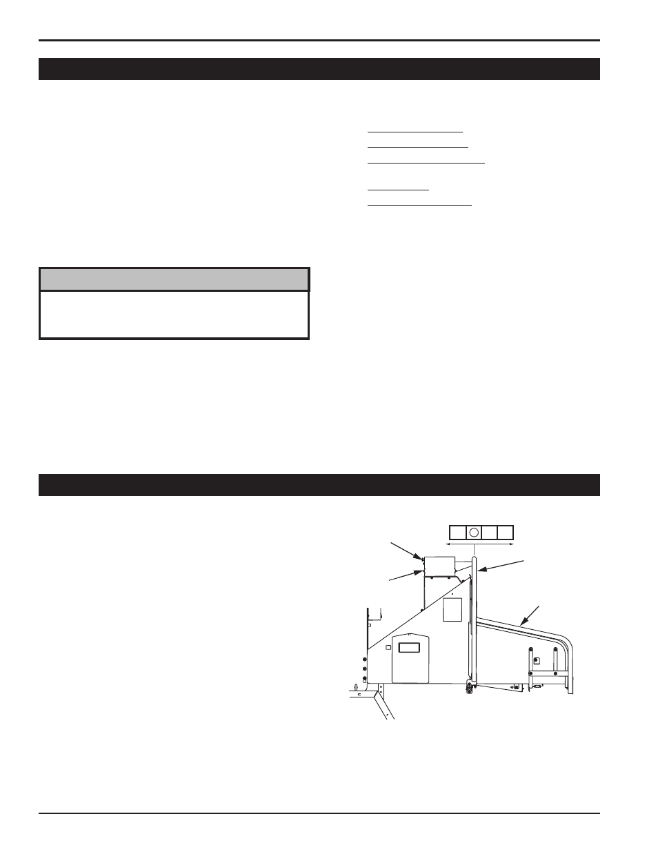
4.8 fEED RoLLER coNTRoL bAR
opERATINg
Start the chipper engine. Bring the machine to 1/4 operating
speed (Section 4.1).
Slowly release engagement handle to engage the drive
belt.
Bring the machine to full throttle.
Engage the hydraulic feed by moving the control bar as
shown in Figure 4.3.
If the chipper jams, reverse the feed by moving the control
bar to the reverse position. Remove the branch and rotate
it before reinserting into the chute again.
1.
2.
3.
4.
5.
Figure 4.3 - Control Arm Operation
The feed roller control bar is used to manually control the rota-
tion of the feed roller.
FORWARD (F) rotation is used to move material into the feed
chute towards the chipper blades.
REvERSE (R) rotation is used to push material out of the feed
chute away from the chipper blades.
STOP is used to halt the rotation of the feed roller.
SAFETY BAR
(S & F MODELS)
RESET/OVERRIDE
BUTTON
(S & F MODELS)
SAFETY BAR
ACTIVATED
(S & F MODELS)
R
REVERSE
R
F
FORWARD
STOP
REVERSE
CONTROL BAR
It is important to bring the engine to full RPM before oper-
ating the chipper. The chipper feed controller requires the
chipper disk to turn at full RPM in order to operate.
NoTE