Second half of clamp. zerk – Echo 76824 Owners Manual v.2 User Manual
Page 15
PN 18280-00 R041306
13
ASSEMBLY
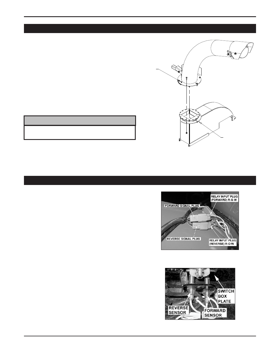
coNNEcTINg ThE sWITch boX
Connect the Relay Input plugs to the Proximity Sensors.
Relay Input Plug (Forward): Red/Green/White wires.
Relay Input Plug (Reverse): Red/Orange/White wires.
Forward/Reverse Sensors: Blue/Black/Brown wires.
The forward/reverse sensors have the same color wires.
use the steps below to verify that they are properly con-
nected to the Relay Input Plugs:
Start engine.
Move the Control Bar to the REvERSE position.
If the feed roller does not rotate in reverse direction,
shut off engine and switch the forward & reverse
signal plugs.
The remaining connectors can be connected by matching
the colored wires.
sETTINg ThE sWITch boX sENsoRs opERATINg
DIsTANcE
Remove the switch box cover.
verify that the sensors are within 2mm (5/64") from the
switch box plate and adjust if needed.
1.
•
•
•
1.
•
•
•
2.
1.
2.
2.11 sWITch boX
2.10 DIschARgE TubE
Attach the discharge tube to the mounting flange on the chip-
per frame. half of the mounting clamp is already attached
to the tube. Slide the tube onto the flange and tighten the
bolts to secure it.
Install the second half of the clamp to the tube and flange.
Grease the zerk and tighten the nuts completely.
Loosen each nut one turn and attempt to rotate the tube.
If it does not rotate freely, loosen each nut 1/2 turn until it
rotates freely.
Rotate the tube 360 degrees and lock it in place with the
handle to make sure it is mounted correctly.
1.
2.
3.
4.
5.
keep nuts as tight as possible while allowing the discharge
tube to freely turn.
NoTE
SECOND HALF
OF CLAMP.
ZERK
Figure 2.3 - Discharge Tube Assembly
Figure 2.5- Switch Box Sensors.
Figure 2.4- Switch Box Connectors.