4 attach discharge tube (cont.), 5 attach discharge tube (76854), 6 connect pto shaft – Echo 71854 User Manual
Page 12
PTO CHIPPERS
10
ASSEMBLY
2.6 connecT PTo sHaFT
Attach chipper to tractor with 3 point hitch. Adjust the
1.
machine up and down to find the shortest distance
between the chipper rotor shaft and tractor PTO. Stop
the machine in the shortest position.
Pull the driveline into two pieces. connect one end to
2.
the tractor PTO and the other end to the chipper rotor
shaft. line up the two halves parallel to each other.
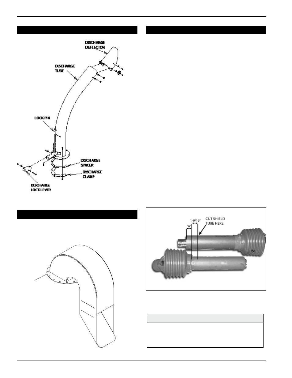
if the shaft of one half extends past the end shield of
the other half as seen in figure 2.5, you will need to
shorten the driveline. if your driveline is not too long,
skip to step 7.
Measure the distance from the end of the driveline tube
3.
to the bottom of the end shield of the other driveline half
(dimension “a” in figure 2.5). Measure and mark the
driveline tube 1-9/16” inward from dimension “a.”
cut the shield tube in the marked position.
4.
using the cut piece of shield tube as your measure-
5.
ment, place the cut piece against the end of the shaft.
Mark and cut the shaft.
repeat step 5 for the other half of the driveline, file both
6.
shaft ends, and slide the two halves back together.
connect the driveline to the chipper rotor shaft using
7.
key stock and two set screws contained in the owner’s
kit.
connect the opposite end of the PTO shaft to the
8.
tractor.
Figure 2.4.2, Attaching the discharge tube (71854, 72854,
71854s, 72854s)
2.4 aTTacH discHarge Tube (conT.)
Figure 2.5, Shortening the driveline
noTe
Minimum and maximum telescoping on the provided
PTO shaft is 20.08" to 26.93". This will leave a 6.85"
overlap. avoid driveline angles over 20 degrees on PTO
shaft when unit is in use.
2.5 aTTacH discHarge Tube (76854)
Bol
1.
t the discharge tube onto the mounting flange with
the eight 3/8" x 7/8" bolts, nuts and washers provided.
Put the bolts through every other hole.
BOLT TO
MOUNTING
FLANGE
Figure 2.4.3, Attaching the discharge tube (76854)