1 attach chipper chute (cont.), 2 safety bar (72854s), 3 hydrostatic control cable – Echo 71854 User Manual
Page 11: 72854s) 9, Important
PTO CHIPPERS
9
ASSEMBLY
Figure 2.1.4, Attaching the extension tray (71854S)
2.1 aTTacH cHiPPer cHuTe (conT.)
2.1.3 aTTacHing exTension TraY (71854s, 72854)
Slide the chute extension tray over the chipper chute.
1.
make sure that you position the lip on the extension
tray behind the lip on the chipper chute. align the
five bolt holes in the chute extension tray with the bolt
holes in the hinge.
insert 3/8" x 1" carriage bolts (included in owner's kit
2.
packaged with chipper) through the four outside holes
on the extension tray and hinge. Secure the bolts with
washers and nuts.
insert one 3/8" x 1-1/2" carriage bolt through the end
3.
of the chute support and middle hole of the extension
hinge and tray. Secure the bolts with washer and nuts.
Secure with hairpin clips.
2.2 saFeTY bar (72854s)
Plug safety bar wire harness into the loose wire har-
1.
ness on the chipper frame.
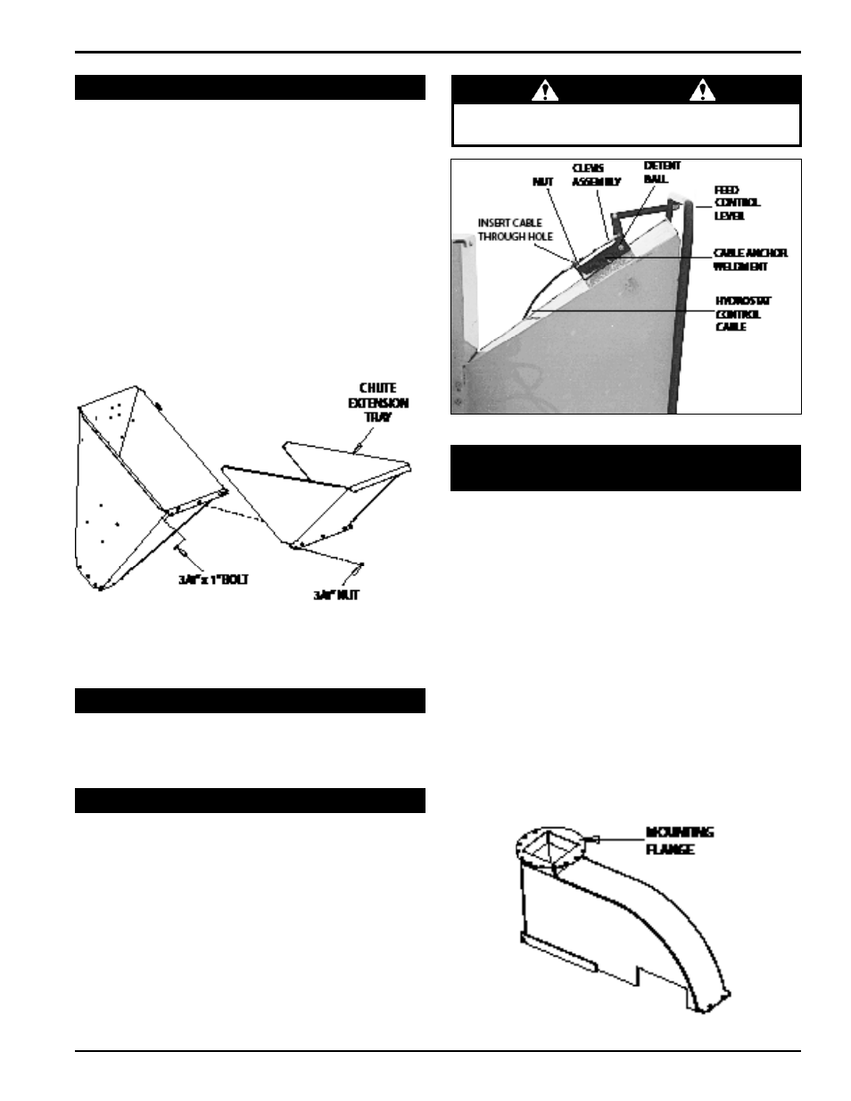
2.3 HYdrosTaTic conTrol cable
On hydraulic feed models, remove the clevis assembly
1.
from the hydrostatic control cable end (see figure 2.3).
remove one nut on the cable end. insert the cable end
into the hole in the cable anchor weldment. replace
the nut and clevis assembly.
attach the clevis assembly to the center hole on the
2.
feed control lever.
Adjust the cable detent ball to contact the detents in
3.
the cable anchor weldment when the control arm is in
the forward or reverse position.
imPorTanT
See Section 4.1 for hydrostatic pump start-up
procedure.
Figure 2.3, Hydrostatic control cable
2.4 aTTacH discHarge Tube (71854,
72854, 71854s, 72854s)
remove half of the spacer and clamp rings that are
1.
connected to the discharge tube with 3/8" x 1-1/4"
bolts.
Slide the tube onto the mounting flange on the chip-
2.
per frame (figure 2.4.1). The discharge clamp should
slide underneath the lip of the flange. Tighten the bolts
to secure it.
reinstall the second half of the spacer and clamp
3.
to the discharge tube. rotate the tube 360 degrees
and lock it in place with the lock pin to make sure it is
mounted correctly.
attach the discharge cap to the discharge tube. con-
4.
nect the cap with 3/8" x 2" bolts through the bottom
hole in the discharge tube. run these bolts through
the inside of the tube, the cap, washer, knob, and
then nut. finish bolting the cap to the tube with 3/8"
x 1" bolts through the end hole in the discharge tube
(figure 2.4.2).
Figure 2.4.1, Mounting flange