5 hydraulic pressure diagnosis, 1 pressure checks and adjustments, Hydraulic pressure diagnosis – JLG G5-18A Service Manual User Manual
Page 79: Pressure checks and adjustments
8.5
G5-18A/2505
Hydraulic System
ALWAYS replace a used o-ring with a new part.
Check all routing of hoses, wiring and tubing for sharp
bends or interference with any rotating members. Install
appropriate protective devices such as tie wraps and
conduit to help shield hoses from damage. All tube and
hose clamps must be tight.
8.5
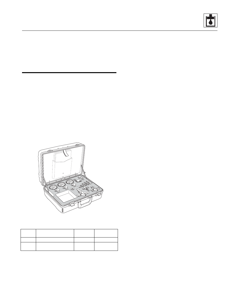
HYDRAULIC PRESSURE DIAGNOSIS
JLG Parts Department has a kit available to use for
hydraulic system maintenance and troubleshooting: the
JLG Pressure Test Kit. The kit is contained in a durable
polyethylene carrying case for demanding field service
conditions.
Pressure Test Kit
The hydraulic pressure test kit is used to pressure test the
various hydraulic components in the hydraulic system.
The kit includes:
• Gauges for testing high and low pressure circuits
• Fittings, couplers and hoses
Contact JLG Parts Department at 717-485-6472 for
ordering information.
8.5.1
Pressure Checks and Adjustments
In general, follow the steps below whenever conducting
pressure checks and performing adjustments:
1. Park the machine on a firm, level surface. Engage
the park brake, place the transmission control lever
in (N) NEUTRAL, place the neutral lock lever in the (N)
NEUTRAL LOCK position, level the boom and turn
the engine OFF.
2. Pressure tee fittings are conveniently located in each
hydraulic circuit. Install a pressure gauge capable of
measuring at least 10% more pressure than that
which the circuit being checked operates under.
3. Start the engine. Operate machine functions several
times to allow hydraulic oil to reach operating
temperature. The hydraulic oil temperature should
be between 100-120° F (38-49° C). If a temperature
gauge or thermometer is unavailable, the hydraulic oil
reservoir should be warm to the touch.
4. Fully depress the accelerator pedal as required.
Place and hold the joystick in the position needed to
operate the particular machine function being
checked. Continue holding the joystick in position
until pressure readings are taken.
5. Check the pressure gauge reading. It should read as
described in the appropriate section. If the reading is
not as specified, turn the engine OFF and check
other components in the system. Verify that all
related hydraulic components and electrical
switches, sensors, solenoids, etc. are operating
correctly.
6. As a last resort, adjust the appropriate relief valve, if
applicable. Turning the adjustment screw clockwise
will increase the pressure; turning the screw
counterclockwise will decrease the pressure.
Start the engine and check the pressure again. Turn the
engine OFF, operate the auxiliary hydraulic control lever
(on units equipped with the optional auxiliary hydraulic
system), then disconnect or remove the pressure gauge
from the machine.
Part
Number
Description
Approximate
Weight
Price and
Availability
70000652 Hydraulic Pressure Test Kit
10 lbs.
Consult Factory
70000101 Digital Hydraulic Pressure
Test Kit
7 lbs.
Consult Factory
MZ1460