11 switches, solenoids and senders, 1 ignition key switch, Switches, solenoids and senders – JLG G5-18A Service Manual User Manual
Page 121: Ignition key switch
9.21
G5-18A/2505
Electrical System
The cab heater controls are located to the right of the
seat. The control panel consists of a variable speed fan
control knob and a temperature control knob.
a. Cab Heater Controls Removal
Note: After determining which control knob is not
functioning, remove only the suspect control knob. In
order to remove either knob, the cab heater and fan
control panel must be removed from the dash panel.
1. Open the battery cover.
2. Disconnect the battery negative (-) cable at the
battery negative (-) terminal.
3. Remove the screws and backing locknuts from the
cab heater and fan control panel.
4. Pull the control panel out from the dash panel, and if
removing variable speed fan control, remove the cab
harness connector.
5. If removing the temperature control knob, disconnect
the cable connector and remove control knob.
6. Remove the setscrew from the variable speed fan
control knob or temperature control knob.
7. Remove the hex locknut from the suspect control
shaft.
8. Remove the control from the panel.
b. Disassembly
DO NOT disassemble the cab heater and fan controls.
The controls are not serviceable. Replace controls if
found to be defective.
c. Installation and Testing
1. Check that the variable speed fan control is in the
OFF position.
2. If installing the temperature control, attach the cable
connector to the back of the control.
3. Insert the control shaft through the panel, ensuring
that the knob is in the VERTICAL position.
4. Install the hex locknut on the shaft and tighten.
5. Connect the cab harness connector to the variable
speed fan control.
6. Install the control panel screws.
7. Install the setscrew, securing the knob to the control.
8. Connect the battery negative (-) cable to the battery
negative (-) terminal.
9. Close and secure the battery cover.
9.11
SWITCHES, SOLENOIDS AND
SENDERS
9.11.1
Ignition Key Switch
a. Ignition Switch Removal
1. Open the battery cover.
2. Disconnect the battery negative (-) cable from the
battery negative (-) terminal.
3. Remove lower dash panel.
4. Remove the hex nut securing the ignition key switch
to the dash.
5. Reach up under the dash to work the ignition switch
and wiring out of the mounting hole.
6. Disconnect the ignition switch connectors from the
cab harness connectors, and remove the switch
from the machine.
b. Disassembly
DO NOT disassemble the ignition switch. Replace a
defective switch with a new part.
c. Inspection and Replacement
To determine the proper operation of the ignition key
switch, test the wires on the back of the switch for
continuity with an ohmmeter.
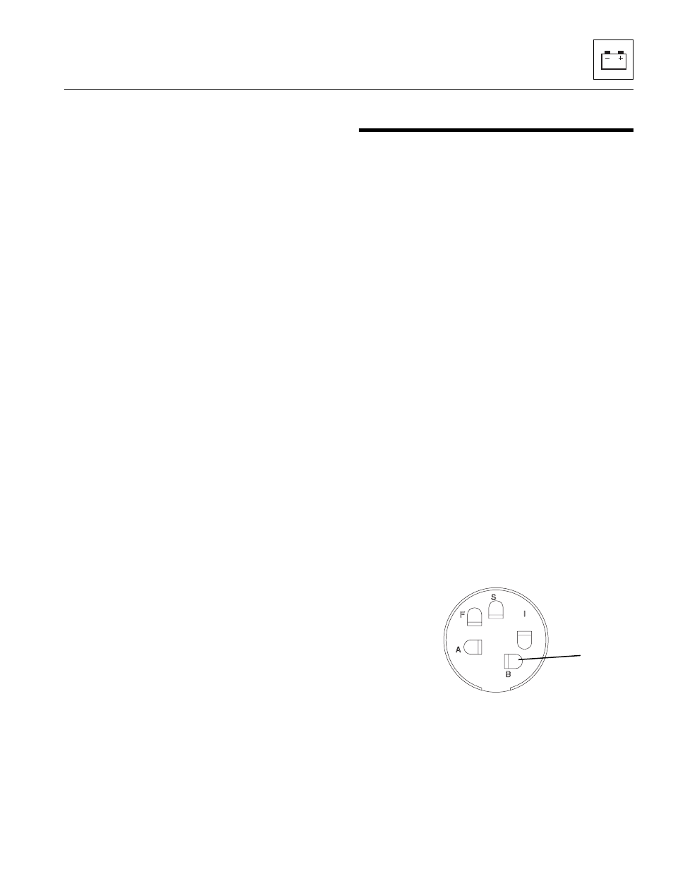
Test the ignition key switch for continuity, by checking
from the BAT terminal (1) to each of the remaining
terminals in their corresponding switch position.
If all terminals do not show proper continuity, replace the
ignition switch.
d. Ignition Switch Installation
1. Connect the ignition key switch to the cab harness
connectors.
2. Reach up and under the dash to work the ignition
switch into the ignition switch-mounting hole on the
lower right side of the dash.
MY2340
1