9 engine coupler, 1 coupler removal, 2 coupler installation – JLG G5-18A Service Manual User Manual
Page 73: Engine coupler, Coupler removal, Coupler installation, Notice
7.9
G5-18A/2505
Engine: Perkins 1104D-44T
13. Refill the hydraulic reservoir (Refer to the
appropriate Operation & Safety Manual for
information concerning the hydraulic oil and filter
change).
14. Reinstall the engine cover, radiator cover and engine
bay access cover.
15. Reconnect the battery terminals, being sure to start
with the positive (+) terminal.
16. Check that all hydraulic, electrical, cooling, fuel and
exhaust system connections are correct and
connected tightly.
17. Run engine to normal operating temperature then shut
off the engine. While the engine is cooling, check for
leaks.
18. Allow the engine to cool. Check the radiator coolant
level, and top off with a 50/50 mixture of ethylene
glycol and water. Replace the radiator cap.
19. Check for leaks from the engine, main hydraulic pump
and lines, transmission, hydraulic reservoir and fuel
tank. Check the levels of all fluids and lubricants. Fill
as required.
20. Obtain and connect an appropriate engine analyzer
or tachometer. Check the engine rpm at full throttle.
If the rpm is not 2370 ±50 rpm, readjust the throttle
limit-stop screw at the throttle pedal within the cab.
21. Purge the hydraulic system of air by operating all
boom functions through their entire range of motion
several times. Check the hydraulic oil level.
22. Check for proper operation of all components.
23. Turn the engine OFF.
24. Install the belly pan.
25. Install the engine cover. Close and secure the cover.
7.9
ENGINE COUPLER
7.9.1
Coupler Removal
1. Remove Hydrostatic transmission. Refer to Section
6.4.1, “Transmission Removal.” Be sure to follow all
described safety guidelines.
2. After transmission has been removed, take out the
12 bolts that attach the Flywheel Cover Plate to the
engine.
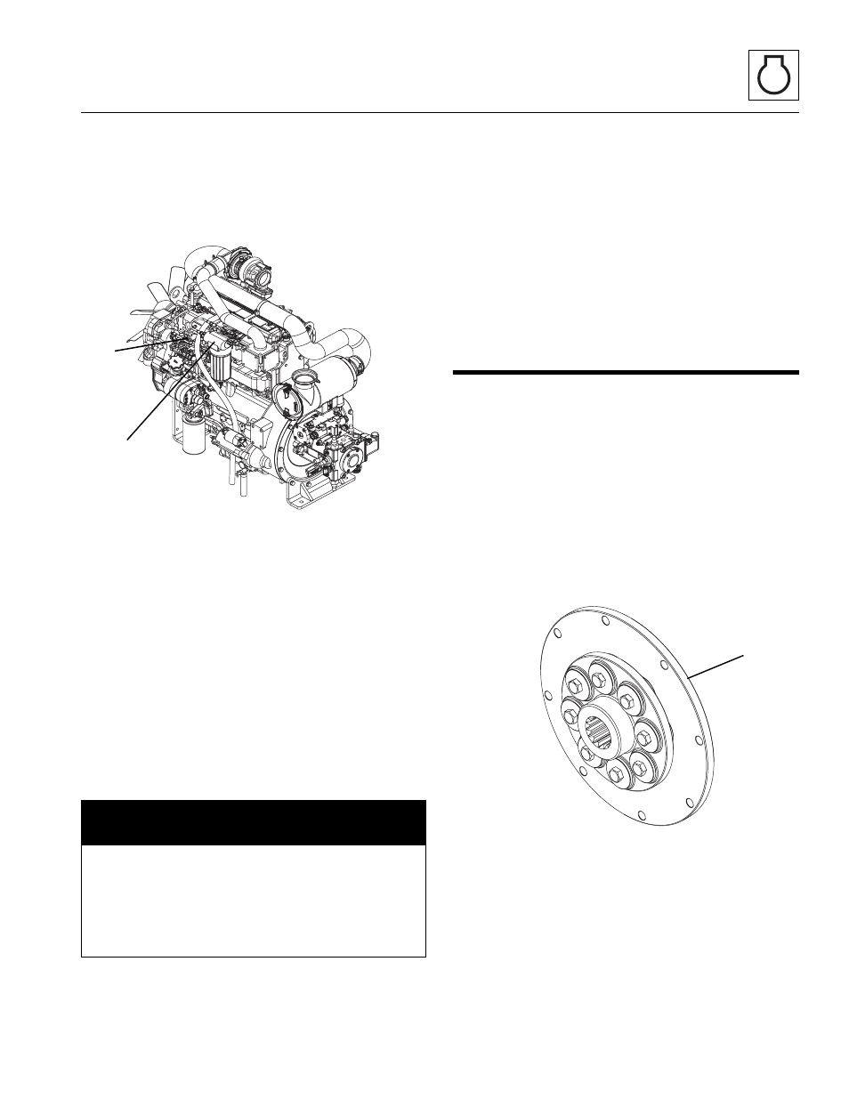
3. Pull off the Flywheel Cover Plate to expose the
coupler assembly (3).
4. Remove the necessary bolts to detach the coupler
assembly.
7.9.2
Coupler Installation
1. Attach the coupler assembly (3) using the necessary
bolts. Torque to 155 lb-ft (210 Nm).
2. Bolt on the Flywheel Cover Plate over the coupler
and flywheel. Torque bolts to 37 lb-ft (50 Nm).
3. Reattach the hydrostatic transmission. Follow all
guidelines in Section 6.4.3, “Transmission
Installation.”
NOTICE
During the full throttle check:
• DO NOT operate any hydraulic function.
• DO NOT steer or apply any pressure to the
steering wheel.
• Keep the transmission in NEUTRAL (N).
MY1890
1
2
MY2550
3