3 first boom section installation, 4 second boom section installation, 5 complete boom removal – JLG G5-18A Service Manual User Manual
Page 25: First boom section installation, Second boom section installation, Complete boom removal
3.5
G5-18A/2505
Boom
3.3.3
First Boom Section Installation
Note: Light lubrication of the boom wear surfaces with a
factory authorized grease is recommended to keep the
boom wear surfaces lubricated properly. Light lubrication
of the boom wear surfaces is also recommended when
the machine is stored, to help prevent rusting.
1. Park the machine on a hard, level surface, place the
transmission control lever in (N) NEUTRAL, engage
the park brake and shut the engine OFF.
2. Place an Do Not Operate Tag on both the ignition
key switch and the steering wheel, stating that the
machine should not be operated.
3. Open the engine cover. Allow the system fluids to
cool.
Note: Grease the boom pivot bore, compensating
cylinder rod ends, lift/lower cylinder rod end and pins
before installing.
4. Using suitable slings, balance the first boom section,
lift and carefully guide the boom into place. Align the
frame pivot bore with the boom assembly pivot bore.
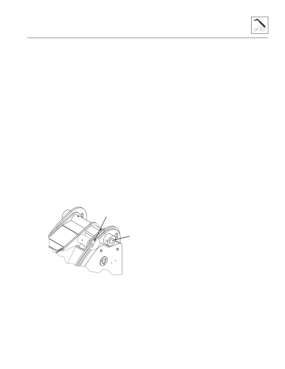
Install boom pivot pin (5) and lock bolt. Apply
Loctite
®
#242 and torque to 66 lb-ft (90 Nm).
5. With the sling still in place, install the compensating
cylinder, pin (6) and lock bolt. Apply Loctite
®
#242
and torque to 66 lb-ft (90 Nm).
6. With the sling still in place, install the rod end of the
lift/lower cylinder, pin and lock bolt. Apply Loctite
®
#242 and torque to 66 lb-ft (90 Nm).
Note: Raising the boom up or down with the sling may
be necessary so the boom, compensating and lift/lower
cylinder bores can be aligned for easier pin installation.
7. Make sure boom section is level, then remove sling.
3.3.4
Second Boom Section Installation
Note: Light lubrication of the boom wear surfaces with a
factory authorized grease is recommended to keep the
boom wear surfaces lubricated properly. Light lubrication
of the boom wear surfaces is also recommended when
the machine is stored, to help prevent rusting.
1. If previously removed, install the extend/retract
cylinder into the rear of the second boom section.
Pin and clip the barrel end of the cylinder in place.
2. Using suitable slings, balance the second boom
section, lift and carefully guide the boom into place.
3. Install the wear pads, shims and bolts to their proper
location at the front inside of the first boom section.
DO NOT tighten the wear pads at this time.
4. Feed the tilt cylinder hoses and if equipped, the
auxiliary hoses through the channel above the
extend/retract cylinder.
5. Install the wear pads, shims and bolts previously
removed from the rear of the second boom section.
DO NOT tighten the wear pads at this time.
6. Uncap and reconnect the extend/retract cylinder
fittings and plugs from extend/retract cylinder tubes.
Attach each tube to the extend/retract cylinder
fittings and tighten until wrench-tight. Mark the fitting,
then tighten each tube firmly 1 to 1,5 flats.
7. Uncap and reconnect the tilt hoses and (if equipped)
auxiliary hoses. Attach both sets to their appropriate
fittings until wrench-tight. Mark the fitting, then
tighten each hose firmly 1 to 1,5 flats.
8. Adjust and shim each wear pad as needed.
9. Start the engine and operate all boom functions
several times to bleed any air out of the hydraulic
system. Check for fluid leaks. Check the hydraulic
fluid level in the tank and add fluid as required.
10. Clean up all debris, hydraulic fluid, etc., in, on, near
and around the machine.
11. Close and secure the engine cover.
3.3.5
Complete Boom Removal
1. Remove any attachment from the quick switch
assembly.
2. Be sure there is enough room in front of the machine
to allow the boom sections to be removed. Park the
machine on a hard, level surface, fully retract the
boom, Raise the boom to allow access to the lift
cylinder and the comp cylinder pivot pins, place the
transmission control lever in (N) NEUTRAL, engage
the park brake and shut the engine OFF.
MY1980
6
5