9 extend/retract cylinder removal, Extend/retract cylinder removal – JLG G5-18A Service Manual User Manual
Page 28
Boom
3.8
G5-18A/2505
6. With the sling still in place, install the rod end of the
lift/lower cylinder, pin and lock bolt. Apply Loctite
®
#242 and torque to 66 lb-ft (90 Nm).
Note: Raising the boom up or down with the sling may
be necessary so the boom, compensating and lift/lower
cylinder bores can be aligned for easier pin installation.
7. Uncap and reconnect the extend/retract cylinder
fittings and plugs from extend/retract cylinder tubes.
Attach each tube to the extend/retract cylinder
fittings and tighten until wrench-tight. Mark the fitting,
then tighten each tube firmly 1 to 1,5 flats.
8. Uncap and reconnect the tilt hoses and (if equipped)
auxiliary hoses. Attach both sets to their appropriate
fittings until wrench-tight. Mark the fitting, then
tighten each hose firmly 1 to 1,5 flats.
9. Start the engine and operate all boom functions
several times to bleed any air out of the hydraulic
system. Check for fluid leaks. Check the hydraulic
fluid level in the tank and add fluid as required.
10. Check clearance (1) between the tilt hoses (and if
equipped) auxiliary hoses and the front of the
extend/retract cylinder trunnion. There should be
approximately 1/2 in. (12,7 mm) of clearance.
11. If adjustment is needed, loosen the tilt tubes (and if
equipped) auxiliary tubes. Move tubes to achieve the
proper clearance.
12. Clean up all debris, hydraulic fluid, etc., in, on, near
and around the machine.
13. Close and secure the engine cover.
3.3.9
Extend/Retract Cylinder Removal
1. Remove any attachment from the quick attach
assembly. Refer to Section 3.5, “Quick Attach
Assembly.”
2. Park the machine on a hard, level surface, extend
the boom to gain access to the extend/retract
cylinder pin in the second boom section
(approximately 3 ft (1 m), level the boom assembly,
place the transmission control lever in (N)
NEUTRAL, engage the park brake and shut the
engine OFF.
Note: The boom must be properly aligned (level) with
the access hole at the rear of the frame to allow removal
of the extend/retract cylinder barrel mounting pin.
3. Place a Do Not Operate Tag on both the ignition key
switch and the steering wheel, stating that the
machine should not be operated.
4. Open the engine cover. Allow the system fluids to
cool.
5. Remove the battery negative (-) cable from the
battery negative (-) terminal.
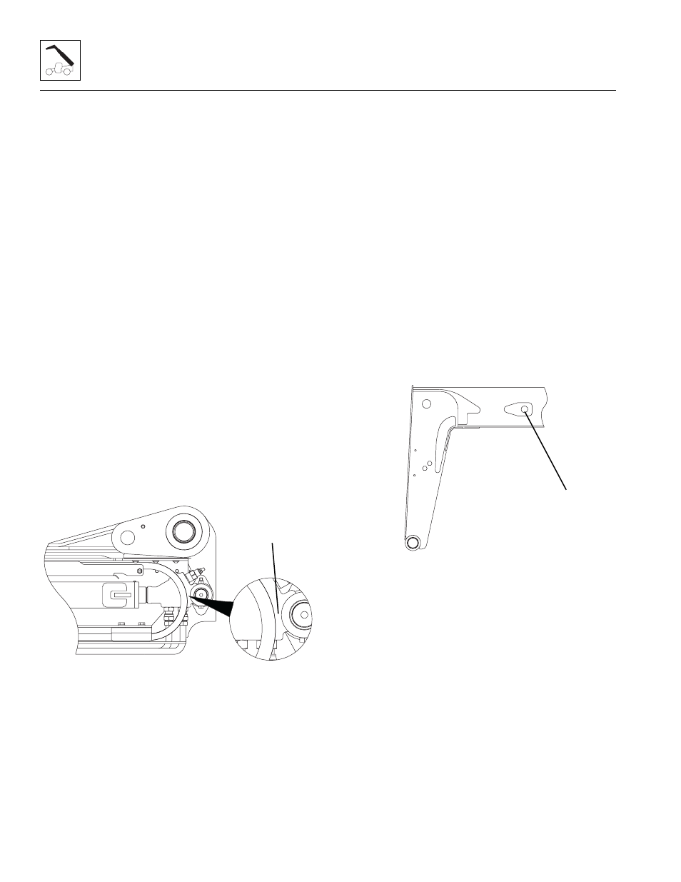
6. Remove the cylinder rod eye retaining clips and
mounting pin (2) at the side of the second boom
section.
7. Loosen and remove the hose clamps and cover
plate (3) from the rear of the boom assembly.
8. Label and disconnect the tilt and auxiliary hydraulic
hoses attached to the machine at the tubes on top of
the boom (4). Plug and cap the hose ends to prevent
dirt and debris from entering the hydraulic system.
9. Loosen and remove the extend/retract cylinder tubes
at the rear of the first boom section. Plug the tube
ends to prevent dirt and debris from entering the
hydraulic system.
MY2000
1
MY2680
2