Advance Adapters 50-9103 User Manual
Page 2
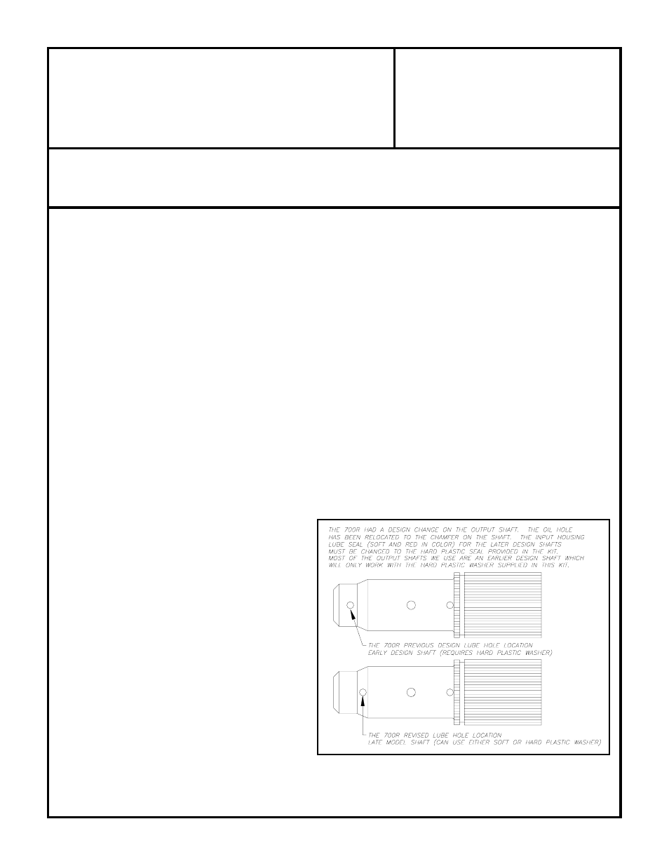
GM 700R-4 AUTOMATIC TO JEEP NP231
T/C (21-SPL) upgrading to a 87-95 23-SPL
ADVANCE ADAPTERS INC.
P/N: 50-9103
P.O. Box 247, 4320 Aerotech Center Way
New Item: (11/93)
Paso Robles, CA 93447
PAGE 2 OF 4
Telephone: (800) 350-2223
Fax: (805) 238-4201
Page Rev. Date:
02-11-13
SPECIAL NOTE:
The components packaged in this kit have been assembled and machined for specific type of conversions. Modifications to any of the
components will void any possible warranty or return privileges. If you do not fully understand modifications or changes that will be required to complete your conversion,
we strongly recommend that you contact our sales department for more information. This instruction sheet is only to be used for the assembly of Advance Adapter
components. We recommend that a service manual pertaining to your vehicle be obtained for specific torque values, wiring diagrams and other related equipment.
These manuals are normally available at automotive dealerships and parts stores.
support is designed around replacement of a manual transmission. If you are replacing an automatic transmission, you
will find that the crossmember support will hang too far down when it is bolted to the bottom of our new adapter housing.
We suggest that you purchase a crossmember support from the manual transmission application to simplify this problem.
The transfer case shift linkage is mounted in two different designs. Jeep Wranglers 1987-96 will require shifter bracket
No. 715523, while Cherokee conversions will require shifter bracket No. 715524. Some applications will the purchase
of a stock Jeep bracket #53004280. This is the most universal for YJ Wranglers. TJ conversions will need to space the
body bracket to use the stock linkage.
ASSEMBLY PROCEDURES:
1.
The output shaft provided by Advance Adapters should be installed by a an experienced transmission tech.
2.
Trial fit the adapter on the transmission. Check to see that the casting seats flush to the transmission case.
3.
Trial fit the transfer case to the adapter and transmission. Check for spline engagement, and shaft depth into the input
coupler of the transfer case.
4.
If the transfer case does not mate flush against the casting,
DO NOT DRAW IT TOGETHER WITH THE
FASTENERS. SEVERE DAMAGE WILL OCCUR.
If interference is detected, the output shaft must be shortened
to a flush stickout with reference to the casting.
Automatic AW4 and AX4/AX5 manual applications, where the
factory output shaft does not protrude beyond the stock adapter, will need shaft modifications.
Cutting the
shaft will require a cut off disc to cut the outer edges and a hacksaw to cut through the center. If you are unsure
about cutting, please call Advance Adapters toll free at 1-800-350-2223. If you do not have the ability to cut your
shaft, a 1" spacer is available (P/N 51-0404).
5.
Press the seal into the casting with the open side toward the transmission.
6.
Install the rubber o-ring on the transmission side of the adapter. A thin bead of silicone should be applied as a sealant.
7.
The four 10mm X 40mm Socket Head Cap
Screws are then used to secure the casting to the
transmission.
8.
Two rotations are provided on the casting. Choose
the rotation that best suits your application.
9.
Studs and nuts are provided for securing the
transfer case.
10. Two of the positions on the rotation will require
removal of two studs from the transfer case and
substitution by the two 3/8"-16 x 1-1/4" Socket
Head Cap Screws. This is due to lack of wrench
clearance around the casting.
11. Use silicone sealant on both sides of the transfer
case gasket. Use Loctite on all bolts.