Warning, Danger, Caution – Snorkel TB85J User Manual
Page 65
Chapter 10 – Emergency Operation
TB80/TB85J – 0112477
61
A
Warning
The aerial platform is free to move when the drive
hubs are disabled. Death or serious injury can re-
sult. Securely fasten the tow vehicle to the aerial
platform before disabling the drive hubs.
Use the following procedure to manually disengage the
drive hubs and tow the machine.
1. With the machine in the stowed position, remove the
tow bar from the storage cradles at the rear of the
chassis and lay the tow bar near the front of the chas-
sis.
A
Danger
Pinch points may exist between machine compo-
nents. Death or serious injury can result from be-
coming trapped between components. Do not at-
tach the tow bar to the tow vehicle until the coun-
terweight is to the side of the chassis.
2. Rotate the turntable, until the counterweight is to the
side of the chassis, to allow room to attach the tow
bar.
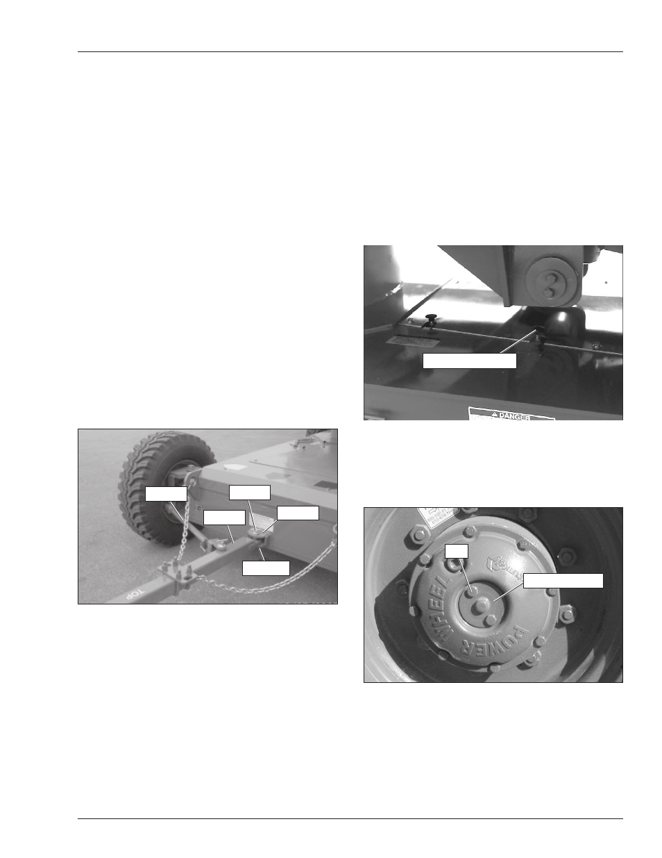
3. Attach the tow bar (refer to Figure 10.6) to the tow
lug with the tow pin and snap pin.
Figure 10.6 – Tow Bar Connection
4. Attach the tie rod to the tow bar and the right hand
steering yoke.
A
Caution
Left hand turns will be restricted if the tow chains
are not properly installed. Damage to the tie rod
could result. Make certain the tow chain on the right
side of the machine goes over the tie rod and not
under it.
5. Attach the two tow bar chains to the tie-down lugs.
Make certain that the chain goes over the tie rod as
shown in Figure 10.6.
6. Attach the ring end of the tow bar to the tow vehicle.
7. Rotate the turntable so the counterweight is back at
the front of the chassis. Raise the platform about 3
′
(1 m) above the ground.
8. Shut the engine off and turn the battery disconnect
switch off.
9. Pull the steering float valve knob up and twist it to
lock it in position. The knob is located on the top of
the chassis, below the boom lift cylinder (refer to Fig-
ure 10.7).
Figure 10.7 – Top of Chassis
10. At each drive wheel, remove the two bolts from the
disconnect plate (refer to Figure 10.8). Turn the plate
over so the nipple points inward. Reinstall the two
bolts.
Figure 10.8 – Drive Wheel
11. Do not exceed 10 mph (16 km/h) when towing. Use
caution when traveling around a curve or when turn-
ing a corner. If the tow bar contacts the chassis the
steering mechanism might be damaged or the tow
vehicle and the aerial platform could jackknife.
Bolt
Disconnect Plate
Steering Float Valve
Tow Lug
Tow Bar
Tow Pin
Snap Pin
Tie Rod