Caution – Snorkel TB85J User Manual
Page 38
Chapter 7 – Prestart Inspection
34
TB80/TB85J – 0112477
Figure 7.9 – Fluid Level Indicator
A
Caution
Not all hydraulic fluid is suitable to use in the hy-
draulic system. Some have poor lubricating char-
acteristics and can increase component wear. Only
use hydraulic fluid as recommended.
If necessary, remove the filler cap and add fluid of the
proper type. Refer to Chapter 2 for the proper type and
grade of hydraulic fluid to use. The need to regularly add
fluid indicates a leak that should be corrected.
The sight glass on the reservoir has an internal thermom-
eter to measure the fluid temperature. The temperature
should be less than 200°F (93°C).
Fluid Filter
Checking the condition of the hydraulic fluid filter is part
of the machine maintenance schedule and should not be
performed by the operator.
Hoses, Tubes, and Fittings
Inspect all hydraulic hoses, tubes, and fittings for wear,
leakage, or damage (refer to Figure 7.10). Make sure the
hoses are properly routed to avoid sharp edges, kinking,
and scuffing. Inspect the tubes for dents or other damage
that may restrict fluid flow. Make sure all hoses and tubes
are held firmly in their support brackets.
Figure 7.10 – Hoses, Tubes, and Fittings
Hydraulic fluid leaks are easily visible on the ground.
Check under the chassis for fluid that has leaked.
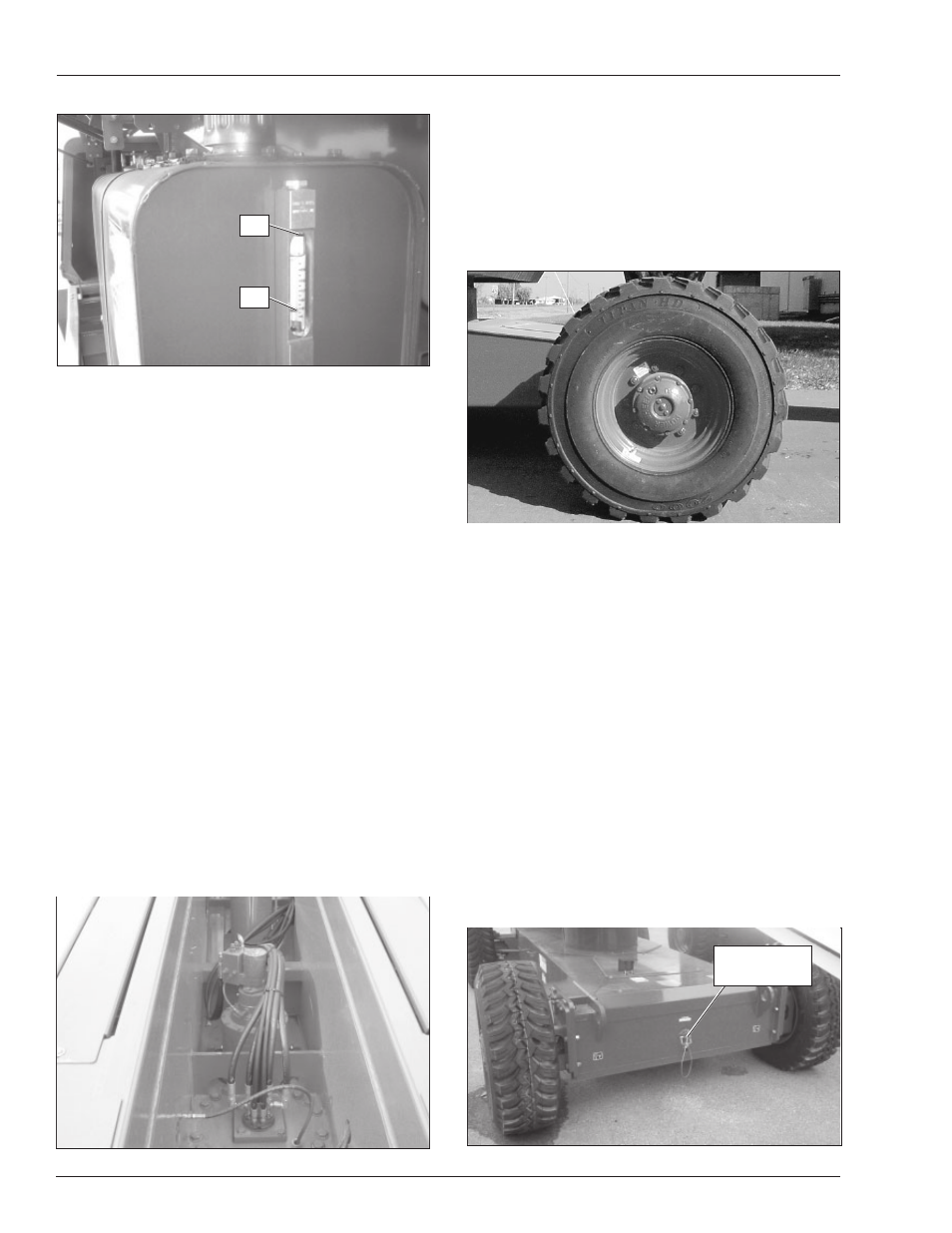
Tires and Wheels
Visually inspect the tires and wheels (refer to Figure 7.11)
to make sure they are suitable for service. Check the
wheel lug nuts to see that none are missing, damaged,
or loose.
Figure 7.11 – Tires and Wheels
The aerial platform has foam filled tires. Foam filled tires
do not have a pressure decal or a valve core.
Inspect for large holes or cuts where foam is coming out
of the tire. Look for large imbedded objects, such as angle
iron, that can rip a tire open.
Punctures caused by bolts, screws, or nails are not a
problem for foam filled tires.
Axle/Boom Interlock
Test for proper operation of the axle/boom interlock sys-
tem from the lower controls with no material or personnel
in the platform.
With the axles retracted and the pin properly locked in
position in the top hole (refer to Figure 7.12), operate the
boom up and extend functions. The boom should only
raise to a few degrees above horizontal and it should only
extend approximately one foot.
Figure 7.12 – Rear Axles Retracted
Full
Add
Pin Locked In
Top Hole