Snorkel TB85J User Manual
Page 41
Chapter 7 – Prestart Inspection
TB80/TB85J – 0112477
37
Flashing Light
If the machine is equipped with an optional flashing light,
visually check to see that it flashes. The light should flash
when the engine is running.
Sandblast Protection Kit
The optional sandblast protection kit protects the cylin-
ders from abrasion while sandblasting or from paint
overspray. Rubber covers protect each cylinder rod as it
extends and retracts. The covers prevent sand and paint
from damaging the cylinder seals and rod.
Inspect the covers while operating the machine to ensure
they are securely fastened and completely cover the cyl-
inder rod. Make sure there are no holes in the covers.
Structures
Visually inspect all weldments and related components.
It is important to inspect the fasteners that connect the
components.
Weldments
Visually inspect all weldments for abnormal wear, abra-
sion, or deformation that could cause interference between
moving parts.
Inspect the welds on the structural components. Pay
particular attention to boom welds. The area to be in-
spected should be clean and free of dirt and grease. Look
for visible cracks in the weld and at the weld to parent
material joint. A bright light may be used to provide ad-
equate visibility of the inspection area.
Slide Pads
The main boom has slide pads (refer to Figure 7.18) be-
tween the main and tip boom sections.
Figure 7.18 – Slide Pads at Tip End of Boom
Use the lower controls to raise the main boom to hori-
zontal. Extend the tip boom about 1
′ (30 cm). Visually
inspect the slide pads to make sure they are in place
and are not obviously loose.
Inspect the surface where the pads contact the interme-
diate and tip booms. The paint must be in place with no
signs of bare metal.
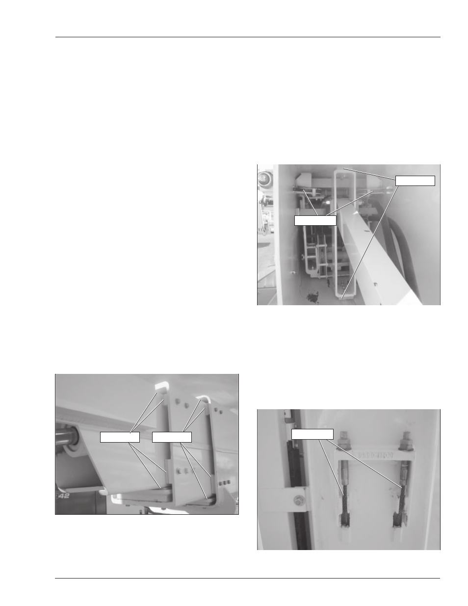
The extension cylinder support bracket has slide pads
(refer to Figure 7.19) that can be inspected by looking
into the base end of the main boom.
Figure 7.19 – Extension Cylinder Support Bracket
Inspect the surface where the pads contact the main
boom. The paint must be in place with no signs of bare
metal.
Wire Ropes
Visually inspect the wire ropes where they are connected
to the outside of the main boom. There are two wire rope
connections on the bottom of the tip end of the main
boom (refer to Figure 7.20).
Figure 7.20 – Bottom of Main Boom at Tip End
Slide Pads
Slide Pads
Slide Pads
Wire Ropes
Wire Ropes