Warning, Chapter 4 – safety devices – Snorkel TB125J User Manual
Page 17
T125J/TB125J – 0192214
17
This aerial work platform is manufactured with safety
devices, placards and decals to reduce the likelihood of
an accident. For the safety of all personnel, do not dis-
able, modify or ignore any safety device. Safety devices
are included in the daily prestart inspection.
Warning
The potential for an accident increases when safety
devices do not function properly. Death or serious
injury can result from such accidents. Do not alter,
disable, or override any safety device.
If any safety devices are defective, remove the aerial
platform from service until qualified maintenance person-
nel can make repairs.
Emergency Stop Controls
There is an emergency stop control at the lower and
upper controls.
At the lower controls, the emergency stop is a two-posi-
tion push button (refer to Figure 4.1). Push the emer-
gency stop button in to disconnect power to all control
circuits. Pull the button out to restore power.
Figure 4.1 – Lower Controls
Note
The lower controls override the upper controls. If the
upper control emergency stop button is engaged, the
lower controls can still be used to operate the aerial
platform.
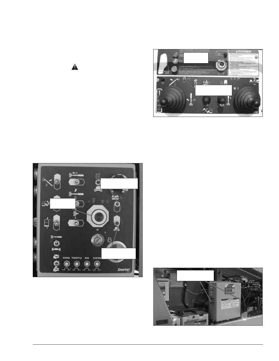
At the upper controls, the emergency stop is a two-posi-
tion push button (refer to Figure 4.2).
Figure 4.2 – Upper Controls
Push the emergency stop button in to disconnect power
to the upper control circuits. Pull the button out to restore
power.
Emergency Power System
The emergency power system includes a backup pump,
motor, and battery. Use this system to operate the boom
and turntable functions to lower the platform if the main
power system fails due to engine or pump failure.
Hold the emergency power switch (refer to Figures
4.1 and 4.2) down to activate the emergency power
system.
The length of time the pump can be operated depends
on the capacity of the battery.
Emergency Bleed Down System
The emergency bleed down system may be used to
lower the booms if the engine will not start and the
emergency power system will not work. The emergency
bleed down system is composed of two pairs of toggle
switches. (Refer to Figures 4.3 and 4.4) One pair of
switches is located on either side of the wiring box. The
second pair of switches is located on either side of the
upper control box.
Figure 4.3 – Wiring Box
Chapter 4 – Safety Devices
Emergency
Stop Button
Engine/Emergency
Power Switch
Ground
Operation Switch
Emergency
Stop Button
Engine/Emergency
Power Switch
Emergency Bleed
Down Switches