Starting from ground control box 8-2, Stabiliser operation 8-2, Standard manual stabiliser operation 8-2 – Snorkel MHP15J User Manual
Page 48: Setting the manually operated stabilisers 8-2, Emergency stop switch, 8-2, 8-5, 9-1, Starting from ground control box, 8-2, Caution, Operation
Be gin at the sec tion en ti tled "Starting From Ground
Con
trol Box", if you in
tend to start and run the
MHP15J from the ground sta tion.
Be gin at the sec tion en ti tled "Starting From Plat -
form Con trol Box", if you in tend to start and run the
MHP15J from the plat form.
■ Starting From Ground Control Box
Be fore you be gin to op er ate the MHP15J from the
ground con trol box, a qual i fied op er a tor must per -
form the "Pre-op er a tional In spec tion" as de scribed
in chap ter 7, of this man ual.
To start the en gine from the ground con trol box do
the fol low ing:
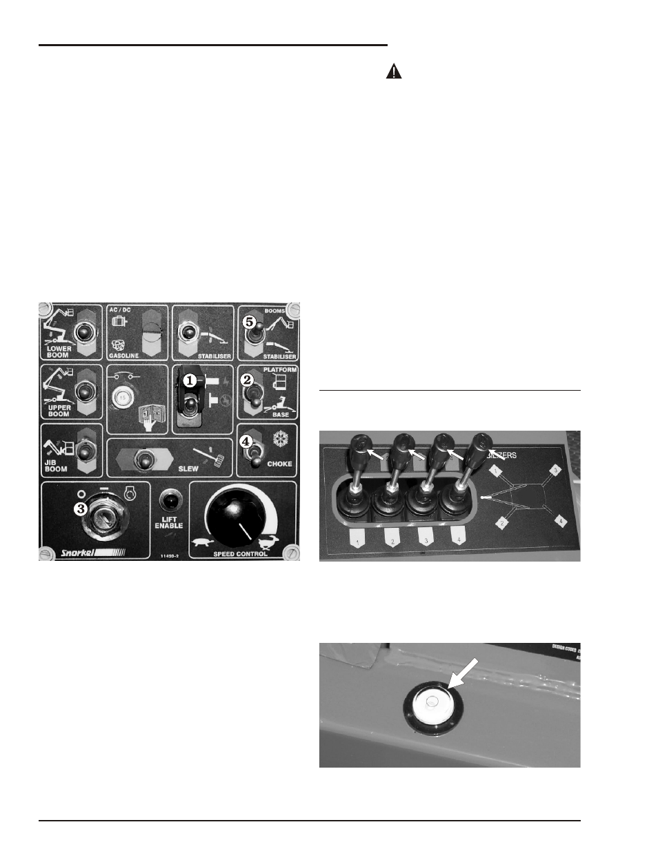
1. Set the Emergency Stop switch to ON
(see Figure 8.3).
Figure 8.3
Figure 8.3 - Ground Control Box Starting
2. Set the Platform/Ground Selector switch
to GROUND (see Figure 8.3).
3. Insert the key (see Figure 8.3) into the
Master Key Switch and turn the key on.
4. If the engine is at ambient temperature
(cold), hold the Choke / Cold Start Switch
(see Figure 8.3) up throughout the next
step.
5. Turn the key to Start and hold it there un til
the en gine starts or for a max i mum time of 6
sec onds. When the en gine starts re lease the
key and the choke switch , if you used it
(see Figure 8.3).
If the engine does not start in 6 seconds turn
the key off and release the choke. Wait 60
seconds before trying to restart the engine
again. Continual cranking of the starter
motor will only result in its damage.
The en gine should now be run ning, and the
MHP15J is ready to be gin work.
■ Stabiliser Operation
❑
Standard manual stabiliser operation
❑
Setting the manually operated stabilisers
The booms must be in the stowed po si tion.
En sure the Boom/Stabiliser Switch (item on the
ground con trol box) (see Fig ure 8.3) is set to sta bi -
lizer.
Lower the stabilisers by push
ing the in
di
vid
ual
valve le vers down (see Fig ure 8.4)
NOTE:
Ensure that the front stabilisers are lowered first
to prevent damage to the jockey wheel.
Figure 8.4
Lower the rear stabilisers and level the ma chine
us ing the level bub ble (see Fig ure 8.5) ad ja cent to
the con trol le vers.
Figure 8.5
page 8 - 2
MHP15J – 11995A
8. Operation
CAUTION