Setting the stabilizers manually 8-3, Starting from platform control box 8-3, Starting from platform control box, 8-3 – Snorkel MHP34J User Manual
Page 47: Setting the stabilizers manually -3, Starting from platform control box -3, Operation
2. Press switch
momentarily to lower the
stabilizers (see Figure 8.4).
The sta
bi
liz
ers will lower and the ma
chine will
“level” au to mat i cally.
NOTE:
Switch is also used to raise the stabilizers to
the stowed position. To do so press switch
momentarily in the raise direction and all the
stabilizers will raise automatically.
NOTE:
Although this option is designed to automatically
set the stabilizers it is also possible to set the
stabilizers independently using the “manual
mode”.
❑
Setting the stabilizers manually
1. Set switch
to manual mode (see Figure
8.4).
2. Operate each switch
(see Figure 8.4) to
raise or lower each stabilizer one at a time.
Use the level bubble (see Figure 2.7 in
Safety Devices Chapter) to check the
machine is level.
NOTE:
When levelling the machine in the manual mode
care is required to ensure that all of the foot
plates are firmly on the ground, the machine is
level and the lift enable light is ON before
entering the platform.
■ Starting From Platform Control Box
Be fore you be gin to op er ate the MHP12/34J from
the plat form con trol box, a qual i fied op er a tor must
per form the "Daily In spec tion and Main te nance" as
de scribed in chap ter 7, of this man ual.
To start the en gine from the plat form con trol box
you must first set some switches on the ground
con trol box, in clud ing set ting the out rig gers and
lev el ing the ma chine.
(See page 8-2 for in for ma tion on set ting the sta bi -
liz ers)
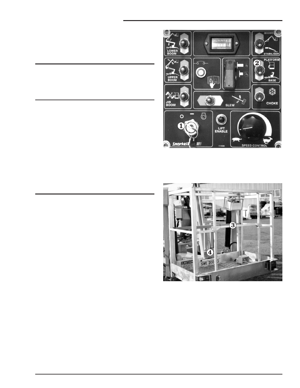
1. Insert the key
into the
Master Key Switch
at the ground control box and turn the key on
(see Figure 8.5).
Figure 8.5
2. Set the
Platform/Ground Selector
(see
Figure 8.5) at the ground control box to
PLATFORM.
Figure 8.6
3. Enter the platform, close the gravity gate
,
and attach the lanyard of your fall restraint
(safety harness) to one of the anchor points
(see Figure 8.6).
MHP12/34J – 11447A
page 8 - 3
8. Operation