Operation considerations 8-2, Starting from ground control box 8-2, Stabilizer operation 8-2 – Snorkel MHP34J User Manual
Page 46: Self levelling stabilizers (option) 8-2, Emergency stop switch, 8-2, 8-4, 9-1, Starting from ground control box, 8-2, Caution, Operation
■ Operation Considerations
To use this chap ter, first de cide whether you will be
start
ing and op er
at
ing the MHP12/34J from the
ground con trol box or the plat form con trol box.
Be gin at the sec tion en ti tled "Starting From Ground
Con
trol Box", if you in
tend to start and run the
MHP12/34J from the ground sta tion.
Be gin at the sec tion en ti tled "Starting From Plat -
form Con trol Box", if you in tend to start and run the
MHP12/34J from the plat form.
■ Starting From Ground Control Box
Be fore you be gin to op er ate the MHP12/34J from
the ground con trol box, a qual i fied op er a tor must
per form the "Daily In spec tion and Main te nance" as
de scribed in chap ter 7, of this man ual.
To start the en gine from the ground con trol box do
the fol low ing:
1. Set the
Emergency Stop
switch
to ON
(see Figure 8.3).
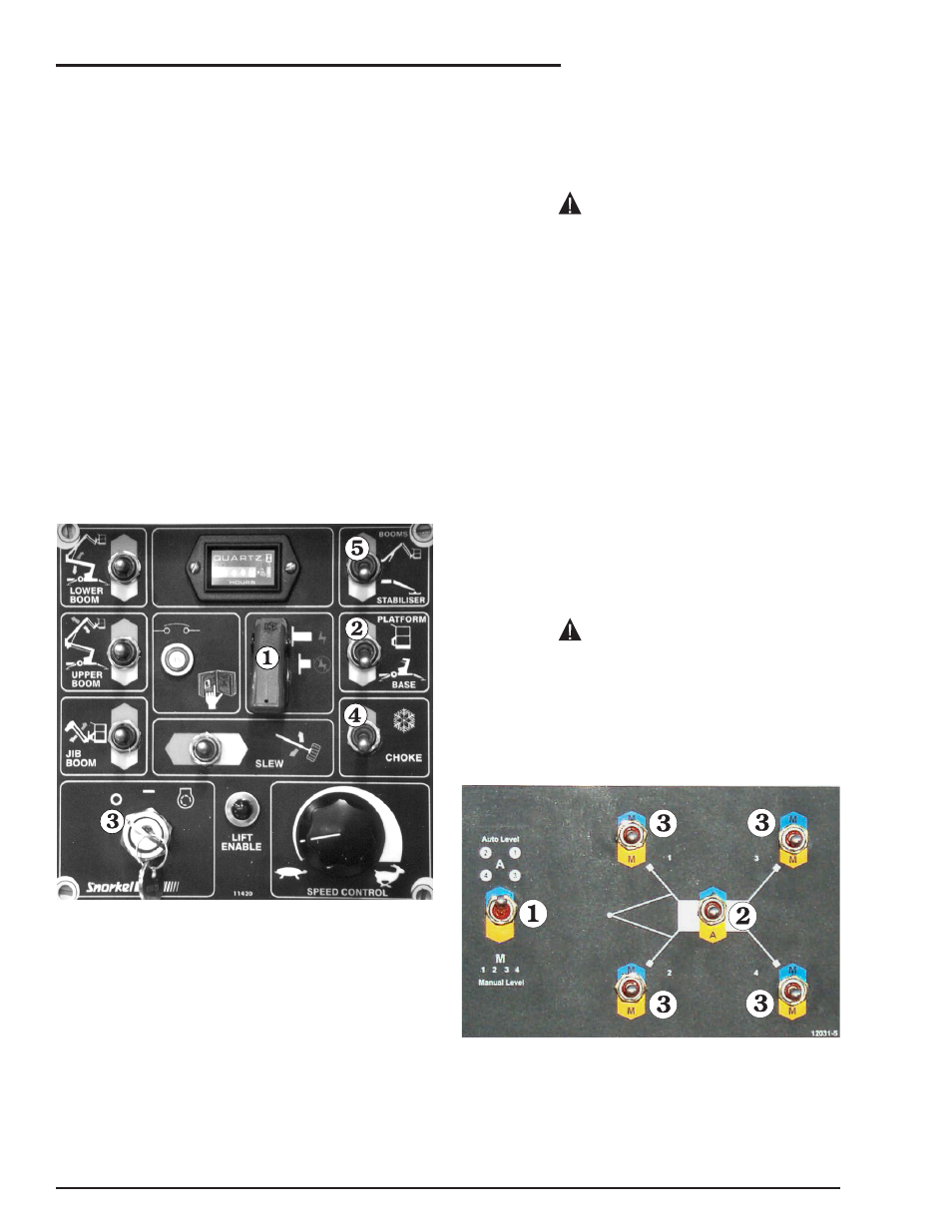
Figure 8.3 - Ground Control Box Starting
2. Set the
Platform/Ground Selector
switch
to GROUND (see Figure 8.3).
3. Insert the key
(see Figure 8.3) into the
Master Key Switch
and turn the key on.
4. If the engine is at ambient temperature
(cold), hold the
Choke / Cold Start Switch
(see Figure 8.3) up throughout the next
step.
5. Turn the key to
Start
and hold it there un til
the en gine starts or for a max i mum time of 6
sec onds. When the en gine starts re lease the
key
and the choke switch
, if you used it
(see Figure 8.3).
If the engine does not start in 6 seconds turn
the key off and release the choke. Wait 60
seconds before trying to restart the engine
again. Continual cranking of the starter
motor will only result in its damage.
The en gine should now be run ning, and the
MHP12/34J is ready to be gin work.
■ Stabilizer Operation
En sure the boom/sta bi lizer switch (item
on the
ground con trol box) (see Fig ure 8.3) is set to sta bi -
lizer.
Ac ti vate the sta bi liz ers with the valve le vers en sur -
ing that the front sta bi liz ers are low ered first to pre -
vent dam age to the jockey wheel.
Ac ti vate the rear sta bi liz ers and level the ma chine
us ing the level bub ble ad ja cent to the con trol le -
vers.
Ensure all four foot plates are in full contact
with the ground and that they are clear of
manhole covers, drains and unstable
ground etc.
■ Self Levelling Stabilizers (Option)
Figure 8.4 - Auto Level Controls
For units fit ted with self lev el ling sta bi liz ers the fol -
low ing ap plies.
1. Set switch
to automatic mode (see Figure
8.4)
page 8 - 2
MHP12/34J – 11447A
8. Operation
CAUTION
CAUTION