System function inspection – Snorkel SL30N Bi-Energy-sn11200+ User Manual
Page 4
4
System Function Inspection
1. Unhook Controller from front guardrail. Firmly
grasp Controller hanger in such a manner that
the Interlock Lever can be depressed, while per-
forming the following checks from the ground.
2. Pull Controller Emergency Stop Button out to
ON
position.
3. Select
ELECTRIC MODE
by turning Controller Key
Switch clockwise to
ON. DO NOT START ENGINE.
4. Turn Drive/Lift Switch to DRIVE position.
5. With the Speed Range Switch first in
HIGH
TORQUE
and then in
HIGH SPEED
, actuate the
Interlock Lever and slowly push the Control Han-
dle to
FORWARD
then
REVERSE
position to check
for speed and directional control. The farther you
push or pull the Control Handle from center, the
faster the machine will travel.
6. Push Steering Switch
RIGHT
, then
LEFT
to check
for steering control.
7. Rehook Controller on front guardrail.
8. Turn the Chassis Key Switch to
CHASSIS
, push
Chassis Lift Switch to the
UP
position and elevate
platform while pushing the Tilt Sensor off of level.
The platform should only elevate about 0.3 m (1
ft.) and the Tilt Alarm should sound. If the plat-
form continues to elevate and/or there is no
alarm, STOP and remove the machine from ser-
vice until it is repaired.
9. Release the Tilt Sensor and fully elevate plat-
form.
10. Visually inspect the elevating assembly, lift cylin-
der, cables and hoses for damage or erratic oper-
ation. Check for missing or loose parts.
11. Lower the platform partially by pushing Chassis
Lift Switch to DOWN, and then check operation of
audible lowering alarm.
12. Push down on the Chassis Emergency Lowering
Switch to check for proper operation, a warning
alarm should sound. Once the platform is fully
lowered, release the switch.
13. Push the Chassis Emergency Stop Button.
14. With only one Emergency Stop Button pushed
down, in the OFF position, operate any control to
verify that all functions are inoperable. Repeat the
test with only the other Emergency Stop Switch
Button OFF. If any function operates with either
Emergency Stop Switch in the OFF position,
STOP and remove the machine from service until
it is repaired.
15. Select DIESEL MODE by turning the Key Switch
fully clockwise to start engine.
NOTE: If the engine is cold, press and hold the
Glow Plug Button on the right hand side of the
Controller for 6 seconds prior to starting.
NOTE: If the engine does not start on the first try,
the Key Switch must be returned to the OFF
position before it can be engaged to start the
engine again.
16. Drive forward and reverse to test the machine
under Diesel power.
17. Close and secure module covers.
18. Turn the Controller Key Switch counterclockwise
to OFF.
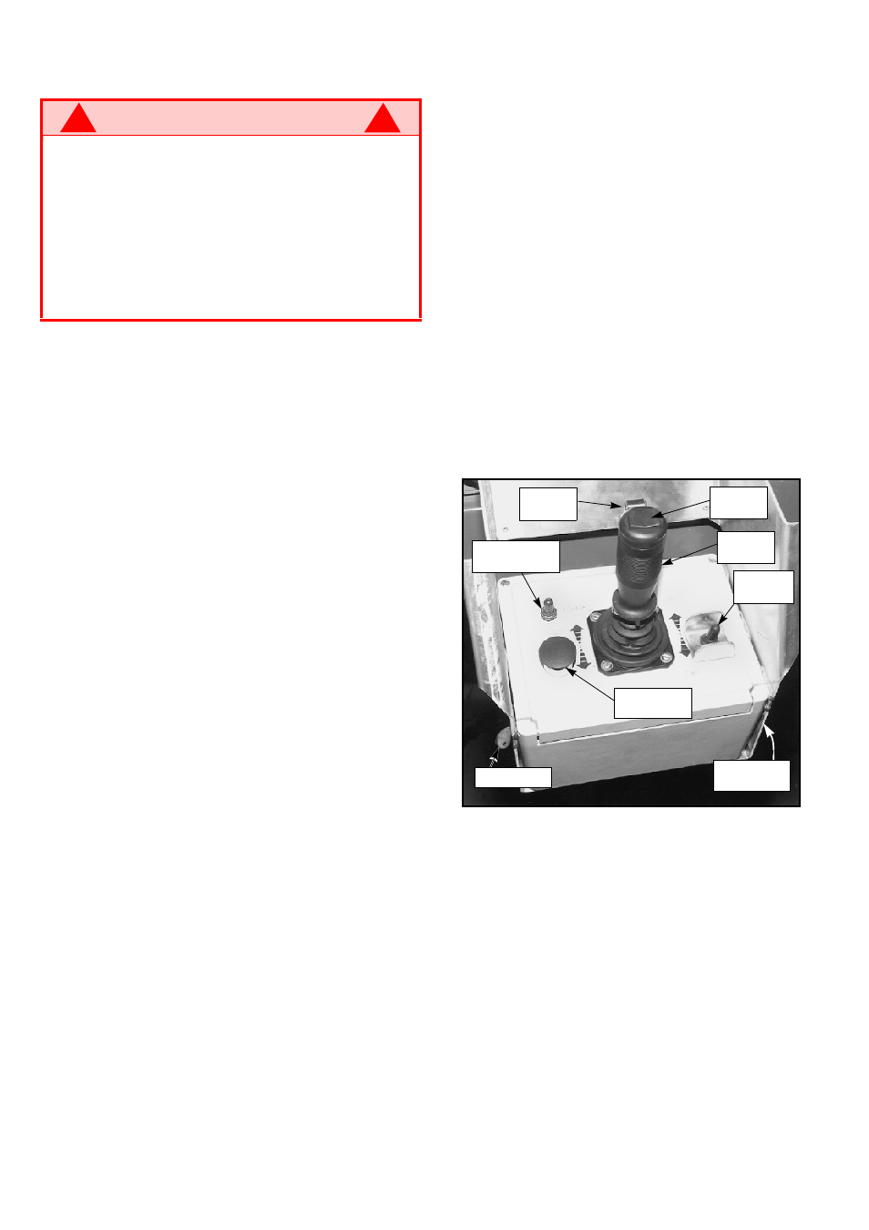
Figure 2: Controller
W A R N I N G
!
!
STAND CLEAR of the work platform while per-
forming the following checks.
Before operating the work platform, survey the
work area for surface hazards such as holes,
drop-offs, bumps and debris.
Check in ALL directions, including above the
work platform, for obstructions and electrical
conductors.
Protect control console cable from possible
damage while performing checks.
Interlock
Lever
Emergency
Stop Switch
Drive/Lift
Switch
Steering
Switch
Control
Handle
Speed Range
Switch
Key Switch
Glow Plug
Button