Technical data sheet – Class1 119971 - Twister Electronic Throttle ANALOG - 120478 EXTERNAL User Manual
Page 12
FORM-ENG-0018 REV A 05-27-03
607 NW 27th Ave
Ocala, FL 34475
Ph: 352-629-5020 or 1-800-533-3569
Fax : 352-629-2902 or 1-800-520-3473
TECHNICAL DATA SHEET
PAGE
11
OF 16
DATE
10/1/2010
PRODUCT GROUP
THROTTLE CONTROL
P/N
119971
REV
1.20
PRODUCT
Twister Electronic Throttle (Analog version)
BY
AMS
Manual P/N 120478
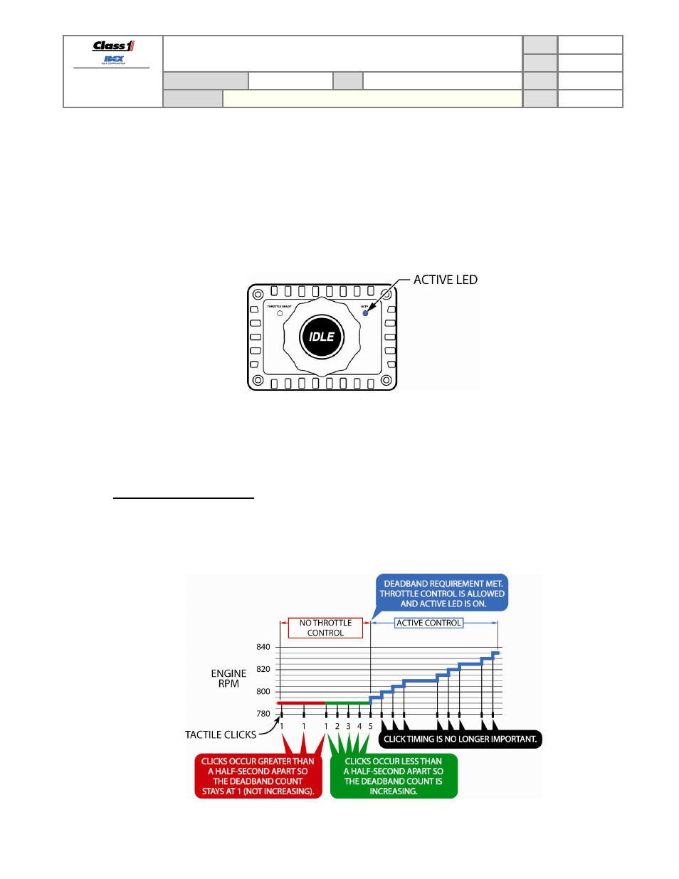
5.3. Controlling engine speed
The Twister allows the operator to control of the engine’s speed by rotating the control knob as long as the interlock is
active.
The blue ACTIVE LED will be ON once the control knob has been rotated in the increase RPM direction enough
clicks to overcome the configured initial deadband (default is 5 clicks).
Each tactile click of the control knob equals a 0.014 volt increase of the analog output signal voltage. With most
manufacturers this equals from 5 to 10 RPM per tactile click.
Figure
7.
Active LED.
The blue ACTIVE LED indicator shows the status of the twister control (see Table 2 in section 3.3). The ACTIVE
LED will blink when the control knob is being rotated while the output signal voltage is already at the configured limit
(minimum or maximum voltage).
5.3.1.
Control knob initial deadband
The Twister requires a number tactile clicks of the control knob in the increase direction before it will allow engine
control. This initial deadband keeps the Twister from inadvertently controlling engine speed caused by accidental
bumps, vibration, etc. The default number of tactile clicks is five (5) with each click occurring within a half-second
of the last. The blue ACTIVE LED activates and throttle control is allowed once the number of tactile clicks has
been established.
Figure 8.
Initial deadband explanation.