T-shoot – Class1 Digital Pressure Gauge User Manual
Page 5
page 5 of 6 pages
Engineering
Standards
Name
Identifier
Instructions
Engineering Standard Number
C1-102190-A
Digital Pressure Gauge
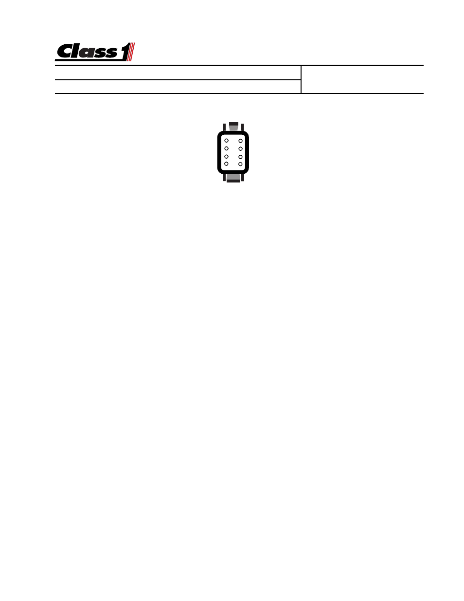
1
2
3
4
8
7
6
5
DTM06-08SA
0462-201-20141 20 Ga.
Wire Insertion View
Switch
8
Pulses IN
7
Sensor Ground
6
System Ground
5
1
N/C
2
PSI IN
3
Sensor +5/10 VDC
4
System Power
The display does not illuminate.
The display must have power at terminal 4 and ground at terminal 5.
With the connector removed, check across pins 4 and 5 for 12 VDC, if 12 volts is
present with the correct polarity, replace the display. If voltage and/or ground is
not present, check the vehicle wiring.
The pressure reading on a discharge or intake gauge does not change.
There is a problem with the pressure transducer or wiring. At the transducer
connector, check for 5 VDC between pins A (ground) and pin B (+5 VDC). These
are sent from the display and must be of the correct polarity for the transducer to
function. Plug the connector into the transducer and check for voltage at the
display between pin 6 (sensor ground) and pin 2 (signal). With zero pressure/
suction at the pump, this voltage should be between 500 mV and 900 mV. As the
pressure in the pump increases, the voltage should increase. If it does not, then
replace the transducer. If the voltage increases, and the display does not change,
perform a default calibration, call Class1 (1-800-533-3569) for instructions. If the
default calibration does not correct the problem, replace the display.
The pressure display reads
SEnS
.
There is a problem with the pressure transducer or wiring. At the transducer
connector, check for 5 VDC between pins A (ground) and pin B (+5 VDC). These
are sent from the display and must be of the correct polarity for the transducer to
function. Plug the connector into the transducer and check for voltage between
Pin A (sensor ground) and pin C (sensor signal) at the transducer. With zero
pressure/suction at the pump, this voltage should be between 500 mV and 900
mV, if it is not, replace the transducer. Check for voltage at the display between
pin 6 (sensor ground) and pin 2 (signal). With zero pressure/suction at the pump,
this voltage should be between 500 mV and 900 mV. If it is not, check the wiring
from the transducer to the display. If the correct voltage is present at pin 2,
replace the display.
T-shoot