Wire view of aem ems – AEM 30-6610 Series 2 Plug & Play EMS User Manual
Page 8
Page 8 of 14
Application Notes for EMS P/N 30-6610
KA24DE, GA16DE, SR20DE
Make: Nissan/Infiniti
Spare
Injector Drivers:
Inj 5, Pin 29
Model:
240SX, Sentra, 200SX, Altima, G20
Spare Injector Drivers:
Inj 6, Pin 30
Years Covered:
1994-1997
Spare Injector Drivers:
Inj 7, Pin 31
Engine Displacement:
1.6L, 2.0L, 2.4L
Spare Injector Drivers:
Inj 8, Pin 32
Engine Configuration:
Inline 4
Spare Injector Drivers:
Inj 9, Pin 116
Firing Order:
1-3-4-2
Spare Injector Drivers:
Inj 10, Pin 117
N/A, S/C or T/C:
N/A
Spare Coil Drivers:
Coil 2, Pin 58
Load Sensor Type:
MAF
Spare Coil Drivers:
Coil 3, Pin 64
MAP Min:
---
Spare Coil Drivers:
Coil 4, Pin 36
MAP Max:
---
Spare Coil Drivers:
---
MAF Min:
0.47 Volts
Boost Solenoid:
PW2, Pin 34
MAF Max:
4.98 Volts
EGT #1 Location:
Pin 62
# Coils:
1 (Distributor)
EGT #2 Location:
Pin 65
Ignition driver type:
0-5V Falling Edge trigger
EGT #3 Location:
Pin 2
EGT #4 Location:
Pin 67
# of Injectors:
4 (Inj 1-4)
Spare 0-5V Channels:
MAP, Pin 66
Factory Injectors:
185cc-250cc
Spare 0-5V Channels:
ADCR11, Pin 9
Factory Inj Resistors:
No
Spare 0-5V Channels:
ADCR13, Pin 24
Injection Mode:
Sequential
Spare 0-5V Channels:
ADCR14, Pin 7
Knock Sensors used:
1
Spare 0-5V Channels:
Knock 2, Pin 68
Lambda Sensors used:
1
Spare Low Side Driver:
LS1, Pin 115
Idle Motor Type:
Pulse Width
Spare Low Side Driver:
LS2, Pin 37 & 57
Main Relay Control:
No (hardware controlled)
Spare Low Side Driver:
LS4, Pin 108
Crank Pickup Type:
Optical
Spare Low Side Driver:
LS8, Pin 114
Crank Teeth/Cycle:
24 (AEM trigger disc)
Spare Low Side Driver:
LS9, Pin 110
Cam Pickup Type:
Optical
Spare Low Side Driver:
LS12, Pin 105
** Cam Teeth/Cycle:
1 (AEM trigger disc)
Check Engine Light:
LS10 , Pin 18
Transmissions Offered:
Manual/Automatic
Spare High Side Driver:
HS1, Pin 11
Trans Supported:
Manual
Spare Switch Input:
Switch 1, Pin 35
Drive Options:
FWD, RWD
Spare Switch Input:
Switch 2, Pin 25
Supplied Connectors:
N/A
Spare Switch Input:
Switch 3, Pin 60
Spare Switch Input:
Switch 4, Pin 22
Spare Switch Input:
Switch 5, Pin 27
A/C Switch Input:
Switch 6, Pin 21
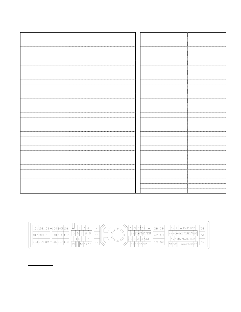
Wire View of AEM EMS
WARNING:
*All switch input pins must connect to ground; the switch should not provide 12V power to
the EMS because that will not be detected as on or off.