AEM 30-6320 Series 2 Plug & Play EMS User Manual
Page 5
Page 5 of 13
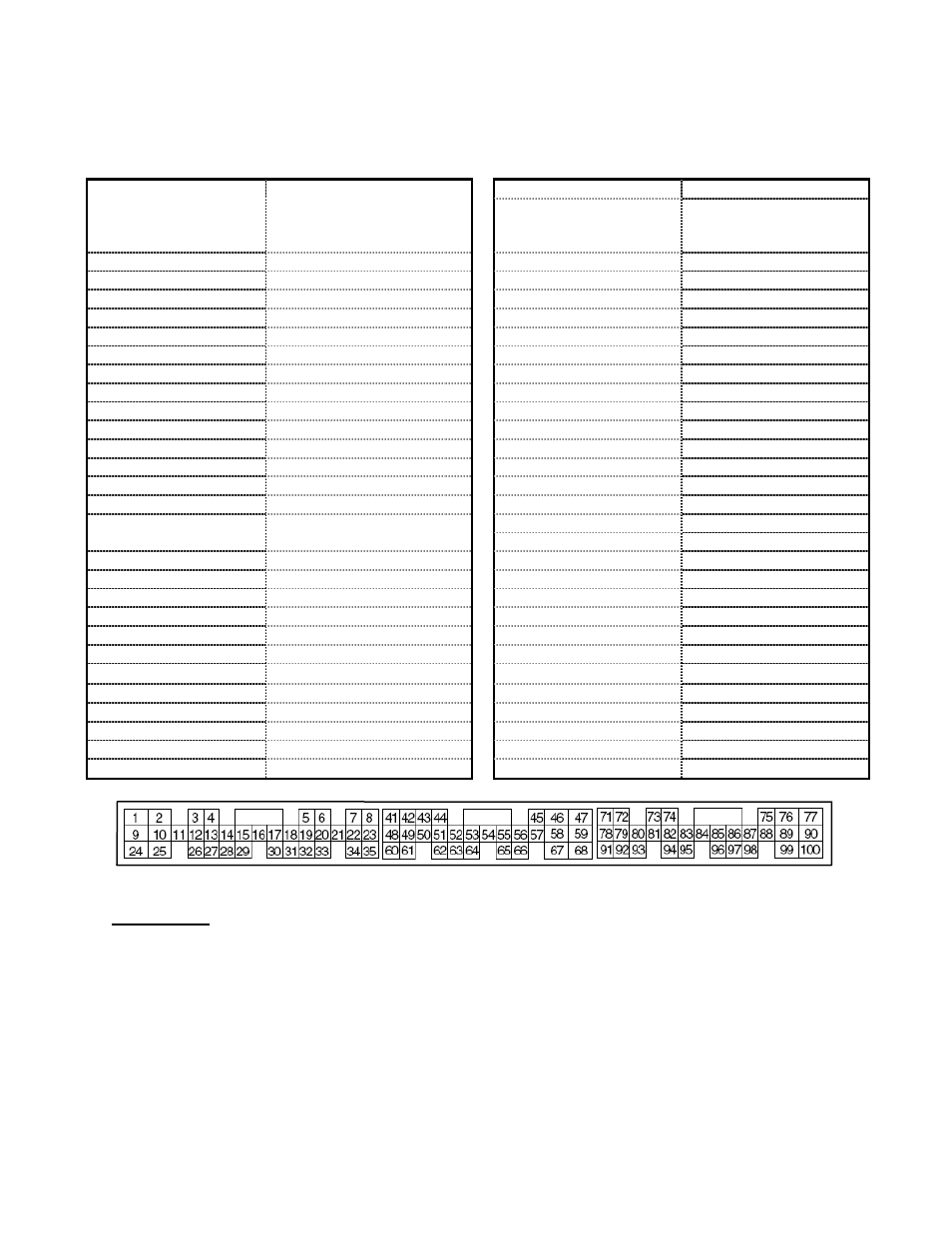
Application Notes for EMS P/N 30-6320
2006 Mitsubishi EVO IX
2005-2006 Mitsubishi EVO IX (Euro)
2003-2004 Mitsubishi EVO VIII (RHD Euro)
Mitsubishi Models:
2006 EVO IX
2005-2006 EVO IX (Euro)
2003-2004 EVO VIII (RHD
Euro)
Spare Injector Drivers:
Inj 7, Pin 8
Spare Injector Drivers:
Inj 8, Pin 6
Spare Injector Drivers:
Inj 9, Pin 19
Engine Displacement:
2.0L
Spare Injector Drivers:
Inj 11, Pin 17
Engine Configuration:
I4
Spare Injector Drivers:
Inj 12, Pin 81
Firing Order:
1-3-4-2
N/A, S/C or T/C:
Turbocharged
Load Sensor Type:
Karman Vortex MAF
Spare Coil Drivers:
Coil 3, Pin 90
# Coils:
2 (wasted spark)
Spare Coil Drivers:
Coil 4, Pin 76
Ignition driver type:
0-5V, Falling Edge trigger
# Injectors:
4 (P&H drivers: Inj1-4)
EGT #1 Location:
Pin 52
Injector Flow Rate:
550 cc/min
EGT #2 Location:
Pin 72
Injector Resistance:
2.5 Ω
EGT #3 Location:
Pin 74
Factory Inj Resistors:
Yes (6 Ω)
EGT #4 Location:
Pin 97
Injection Mode:
Sequential
Spare 0-5V Channels:
MAF, Pin 66
Knock Sensors used:
1
Spare 0-5V Channels:
ADCR11, Pin 93
Lambda Sensors used: 1 (aftermarket wideband:
factory O2 not supported)
Spare 0-5V Channels:
ADCR14, Pin 96
Spare Low Side Driver:
Low Side 1, Pin 3
Idle Motor Type:
Stepper
Spare Low Side Driver:
Low Side 2, Pin 26
Main Relay Control:
Yes (Switch1 in, Coil5 out)
Spare Low Side Driver:
Low Side 8, Pin 35
Crank Pickup Type:
Hall
Spare Low Side Driver:
Low Side 12, Pin 48
Crank Teeth/Cycle:
4
Cam Pickup Type:
Hall
Cam Teeth/Cycle:
2
Check Engine Light:
Low Side 10, Pin 22
Transmissions Offered: M/T, A/T
Spare Switch Input:
Trans Supported:
M/T Only
Spare Switch Input:
Switch 5, Pin 54
Drive Options:
FWD, AWD
A/C Switch Input:
Switch 6, Pin 83
Clutch Switch Input:
Switch 4, Pin 88
WARNING:
Switch input pins must connect to ground; the switch should not provide 12V power to the
EMS because that will not be detected as on or off. Connecting 12V power to Switch pins
may damage your EMS and void your warranty.
Wiring harness destinations for non-USDM vehicles may be different than listed in the
pinout charts below. If installing this EMS on a vehicle not originally sold in the US, please
verify that the vehicle’s wiring harness matches the pinout shown here before installing.
The function of several pins have been changed from the original 30-1320 EMS, please
see the pinout chart for more info.