Connector a, Connector b, Connector c – AEM 30-6030 Series 2 Plug & Play EMS User Manual
Page 16: Connector d, Connector e, Page 16 of 17
Page 16 of 17
Connection Diagram for EMS P/N 30-6030
Pin
2002-2004 Acura RSX K20A2, K20A3
2002-2004 Honda CRV K24A1
2001-2005 Honda Civic D17, Civic Si K20A3
Wire color
AEM EMS
30-6030
EMS I/O
EMS pin description
E17
---
---
Idle 5
Input
Available, switched ground, 1.5A max
E18
Air conditioner clutch relay
Red
Low Side 6
Output
Available, switched ground, 1.5A max
E19
---
---
Idle 6
Output
Available, switched +12V power, 1.5A max
E20
Evaporative emission bypass solenoid valve
Blue/Red
(Grey / Red for K24A1)
Low Side 9
Output
Available, switched ground, 1.5A max
E21
Evaporative emissions canister vent shut valve
Light Green/Red
(White/Red for K24A1)
Injector 9
Output
Available, switched ground, 1.5A max (connected to C7)
E22
Brake pedal position switch
White/Black
Switch 6
Input
Available, switched input
E23
K-line
Light blue
---
---
Not used
E24
SEFMJ (Instrument cluster multiplex communication)
Yellow
Multiplex
Output
Dedicated, used to drive the air conditioning switch
and coolant temperature gauge
E25
---
---
Idle 7
Output
Available, switched ground, 1.5A max
E26
Engine speed pulse
Blue
Low Side 7
Output
PnP for Tacho signal - RPM pulse to instrument cluster
E27
Immobilizer code
Red/Blue (White for K24A1)
---
---
Not used
E28
---
---
High Side 4
Output
Available, switched +12V power, 1.5A max
E29
Service check signal
Brown
ADCR 14
Input
Available, 0-5V input
E30
Write enable signal
Red/White
---
---
Not used
E31
Malfunction indicator lamp (MIL)
Green/Orange
(Green/White for K24A1)
Low Side 10
Output
Available, switched ground, 1.5A max
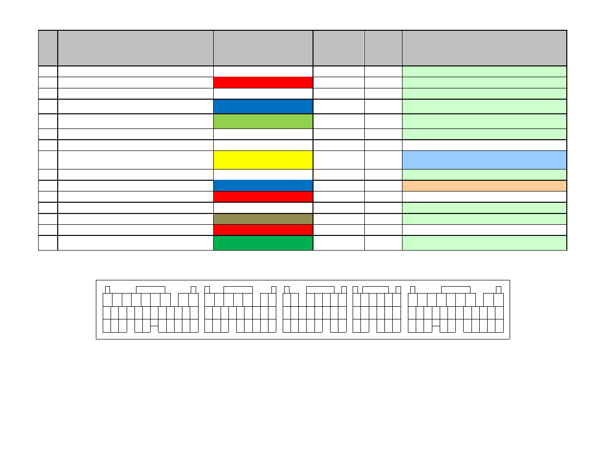
*** Important: Wire View of AEM EMS. Reference diagram below for pin location. ***
22
10
7 8 9
11 12
10
10
12 13 14 15
11
9
8
16
15
14
13
12
11
10
8 9
21
20
19
18
17
16
15
14
13
12
11
10
Connector A
27
23
22
24
26
25
16
19
Connector B
31
29
28
30
17 18
22
20 21
24
23
20
Connector C
18
17
19
21 22
15
Connector D
14
13
17
16
1
2
3
5
4
6
1
9
7
8
1
2
4
3
5
6 7
2
3 4 5
6 7
1 2
3 4 5 6
21
19
18
17
16
15
14
13
12
20
11
Connector E
25
24
23
26
27
31
28 29 30
7
4
1
2
3
5
6
8
9