Connector a, Connector b, Connector c – AEM 30-6030 Series 2 Plug & Play EMS User Manual
Page 15: Connector d, Connector e, Page 15 of 17
Page 15 of 17
Connection Diagram for EMS P/N 30-6030
Pin
2002-2004 Acura RSX K20A2, K20A3
2002-2004 Honda CRV K24A1
2001-2005 Honda Civic D17, Civic Si K20A3
Wire color
AEM EMS
30-6030
EMS I/O
EMS pin description
E1
Immobilizer fuel pump relay
Green/Yellow
Low Side 11
Output
PnP for fuel pump relay
E2
Secondary O2 sensor signal (all except D17A1/6)
Third O2 sensor (2001-2005 Honda Civic D17A6 only)
White/Red
(Red/Blue for K24A1)
O2 #2
Input
Available, 0-5V O2 sensor #2 (connected to C14)
E3
Logic ground 3
Brown/Yellow
---
---
Not used
E4
Sensor ground 3
Pink (White/Green for K24A1)
Sensor Ground
Output
Dedicated, sensor ground
E5
Sensor voltage 3
Yellow/Blue
+5V Sensor
Output
Dedicated, sensor power
E6
Secondary O2 sensor heater control (all except
D17A6)
Third O2 sensor heater control (2001-2005 Honda
Civic D17A6 only)
Black/White
(White/Black for D17A1/6)
Low Side 12
Output
Available, switched ground, 1.5A max
E7
Main relay control
Red/Yellow
Main Relay
Output
Dedicated, ECU activates main relay with switched GND
E8
O2 sensor heater control relay
Orange
Low Side 2
Output
Available, switched ground, 1.5A max
E9
Ignition switch signal 1
Black/Yellow
(Yellow/Black for Civic, CRV)
Ignition Switch
Input
Dedicated, +12V Ignition switch signal from Ign key
E10
---
---
PW 2
Output
Available, switched ground, 1.5A max (connected to
C12)
E11
---
---
Switch 1
Input
Available, switched input (connected to C15)
E12
---
---
Switch 2
Input
Available, switched input (connected to C16)
E13
---
---
Coil 6
Output
Available, switched ground, 1.5A max
E14
Fuel tank pressure sensor
Light Green
ADCR 13
Input
Available, 0-5V sensor
E15
Electrical load detector
Green/Red
ADCR 11
Input
Available, 0-5V sensor
E16
Power steering pressure switch signal
Light Green/Black
Switch 5
Input
Available, switched input
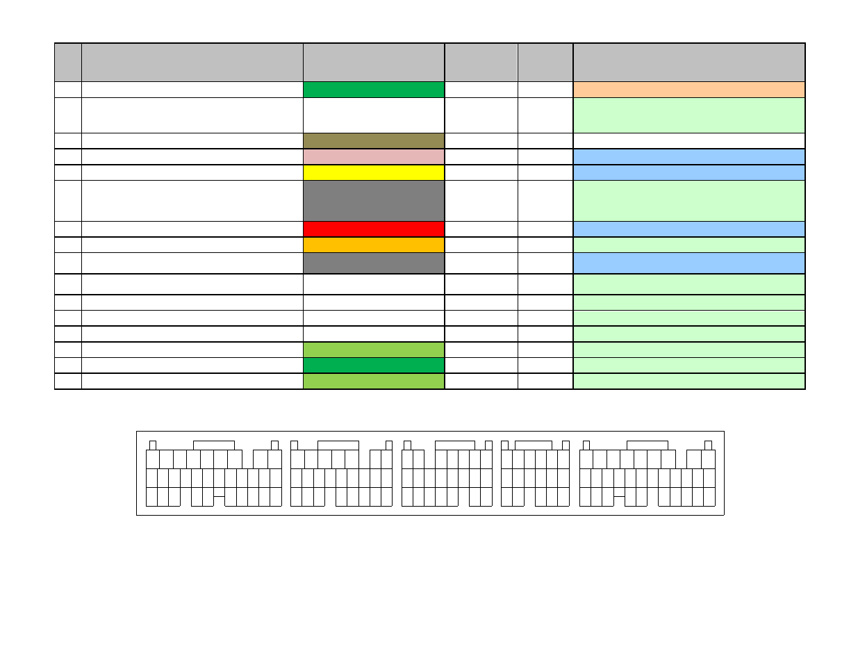
*** Important: Wire View of AEM EMS. Reference diagram below for pin location. ***
22
10
7 8 9
11 12
10
10
12 13 14 15
11
9
8
16
15
14
13
12
11
10
8 9
21
20
19
18
17
16
15
14
13
12
11
10
Connector A
27
23
22
24
26
25
16
19
Connector B
31
29
28
30
17 18
22
20 21
24
23
20
Connector C
18
17
19
21 22
15
Connector D
14
13
17
16
1
2
3
5
4
6
1
9
7
8
1
2
4
3
5
6 7
2
3 4 5
6 7
1 2
3 4 5 6
21
19
18
17
16
15
14
13
12
20
11
Connector E
25
24
23
26
27
31
28 29 30
7
4
1
2
3
5
6
8
9