Connector a, Connector b, Connector c – AEM 30-6030 Series 2 Plug & Play EMS User Manual
Page 10: Connector d, Connector e
Page 10 of 17
Application Notes for EMS P/N 30-6030
K20A2, K20A3, K24A1, D17A1, D17A2, D17A6
Make:
Acura/Honda
Description
Function
ECU Pin #
Model:
Civic, Civic SI, RSX, CR-V
Spare Injector Drivers:
Injector 8
B7 and C5
Years Covered:
2001-2005
Spare Injector Drivers:
Injector 5
B14 and C2
Engine Displacement:
1.7L, 2.0L, 2.4L
Spare Injector Drivers:
Injector 6
B16 and C3
Engine Configuration:
Inline 4
Spare Injector Drivers:
Injector 7
B18 and C4
Firing Order:
1-3-4-2
Spare Injector Drivers:
Injector 10
B23 and C6
N/A, S/C or T/C:
N/A
Spare Injector Drivers:
Injector 9
E21 and C7
Load Sensor Type:
MAP
Spare Coil Drivers:
Coil 6
E13
MAP Min:
0.32V @ -13.9 psi
Boost Solenoid:
PW 2
E10 and C12
MAP Max:
4.84V @ 10.94 psi
Spare PWM Freq Driver (PW 1 inverted):
PW 1i
C19
# Coils:
4
Spare PWM Freq Driver (PW 2 inverted):
PW 2i
C20
Ignition driver type:
0-5V Falling Edge trigger
EGT 1 Location:
EGT 1
B10 and C8
# of Injectors:
4 (Inj 1-4)
EGT 2 Location:
EGT 2
B11 and C9
Factory Injectors:
215cc-330cc saturated
EGT 3 Location:
EGT 3
B12 and C10
Factory Inj Resistors:
No
EGT 4 Location:
EGT 4
B13 and C11
Injection Mode:
Sequential
Spare 0-5V Input Channel:
ADCR 13
E14
Knock Sensors used:
1 (Knock 1)
Spare 0-5V Input Channel:
ADCR 11
E15
Lambda Sensors used:
1 (O2 # 1, wideband sensor
required, original O2 sensor not
supported)
Spare 0-5V Input Channel:
ADCR 14
E29
Spare Low Side Output Driver:
Low side 1
A1
Spare Low Side Output Driver:
Low side 5
B20
Idle Motor Type:
Duty-controlled solenoid PW 1
Spare Low Side Output Driver:
Low side 4
B21
Main Relay Control:
Yes (hardware controlled)
Spare Low Side Output Driver:
Low side 12
E6
Crank Pickup Type:
Hall Effect
Spare Low Side Output Driver:
Low side 2
E8
Crank Teeth/Cycle:
24 + 2
Spare Low Side Output Driver:
Low side 6
E18
Cam Pickup Type:
Hall Effect
Spare Low Side Output Driver:
Low side 9
E20
Cam Teeth/Cycle:
4 + 1
Spare Low Side Output Driver:
Idle 1
A14
Transmissions Offered:
Manual/Automatic
Spare Low Side Output Driver:
Idle 3
B19
Trans Supported:
Manual
Spare Low Side Output Driver:
Idle 5
E17
Drive Options:
FWD and AWD
Spare Low Side Output Driver:
Idle 7
E25
Supplied Connectors:
Plug C with connectors
Check Engine Light:
Low side 10
E31
AEM Extension/patch harness
30-2986 or 30-2986CD
Spare High Side Driver:
High side 2
A22
AEM Plug/pin kit:
N/A
Spare High Side Driver:
High side 4
E28
Spare High Side Driver:
Idle 2
A17
Spare High Side Driver:
Idle 8
A31
Spare High Side Driver:
Idle 4
B24
Spare High Side Driver:
Idle 6
E19
VVC High Side Driver:
High side 3
B1
VTEC High Side Driver:
High side 1
B15
Spare Switch Input:
Switch 1
E11 and C15
Spare Switch Input:
Switch 2
E12 and C16
Spare Switch Input:
Switch 5
E16
Spare Switch Input:
Switch 6
E22
Spare Switch Input:
Switch 3
C17
VTEC Switch Input:
Switch 4
B9
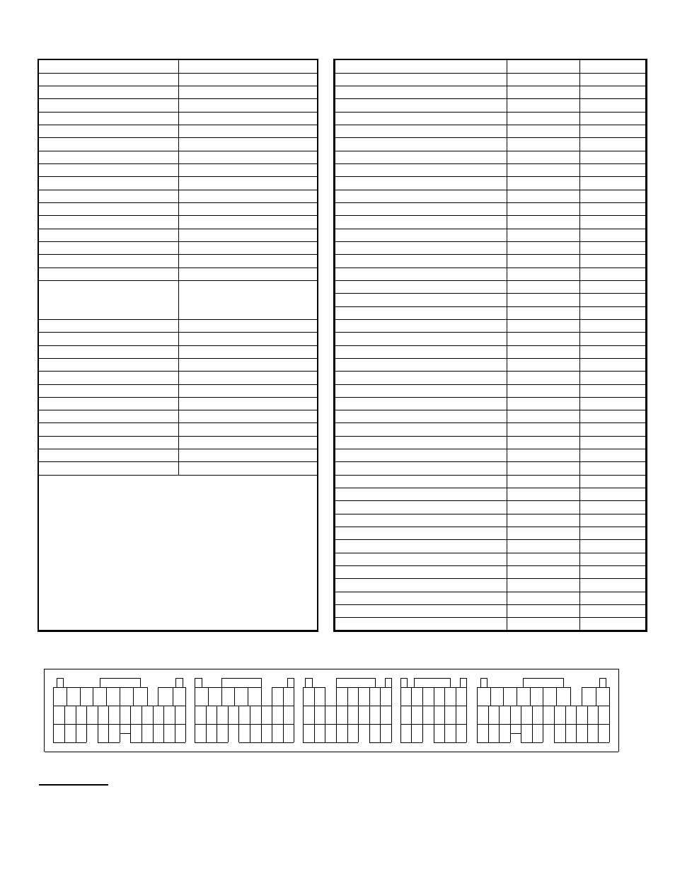
*** Important: Wire View of AEM EMS. Reference diagram below for pin location. ***
22
10
7 8 9
11 12
10
10
12 13 14 15
11
9
8
16
15
14
13
12
11
10
8 9
21
20
19
18
17
16
15
14
13
12
11
10
Connector A
27
23
22
24
26
25
16
19
Connector B
31
29
28
30
17 18
22
20 21
24
23
20
Connector C
18
17
19
21 22
15
Connector D
14
13
17
16
1
2
3
5
4
6
1
9
7
8
1
2
4
3
5
6 7
2
3 4 5
6 7
1 2 3 4 5 6
21
19
18
17
16
15
14
13
12
20
11
Connector E
25
24
23
26
27
31
28 29 30
7
4
1
2
3
5
6
8
9
WARNING:
*All switch input pins must connect to ground; the switch should not provide 12V power to the EMS
because that will not be detected as on or off.