AEM 30-5132M Analog Boost Metric Gauge User Manual
Page 3
Page 3
WHITE – The WHITE wire should be connected to the Analog + input on the
AEM EMS or the analog + input on a similar device.
BROWN – The BROWN wire should be connected to the Analog – input. If the
EMS or similar device does not have a – input, the BROWN wire should be connected
to a sensor ground. If no sensor ground is available, the BROWN wire should be
connected to a power ground. Note: The BROWN wire must be connected in order
to get correct readings from the analog output.
Gauge Start-Up
The boost gauge has an “auto zero” function that accommodates for variances in
atmospheric pressure. Upon powering up, the gauge will take an instantaneous
pressure reading, which will be used as the “zero point” on the faceplate. This allows
the needle position at atmospheric pressure to be “0” for all operating conditions. The
needle will display between 0-35 psi boost for pressures above the current atmospheric
level. The needle will display between 0-30 inHg for “vacuum” pressures below the
current atmospheric level.
Auto Zero Troubleshooting
If the gauge reads “0” or close to “0” while the engine is idling, the auto zero
pressure measurement is inaccurate. This is most likely caused by a power source that
is not on in the On, Run, and Crank positions.
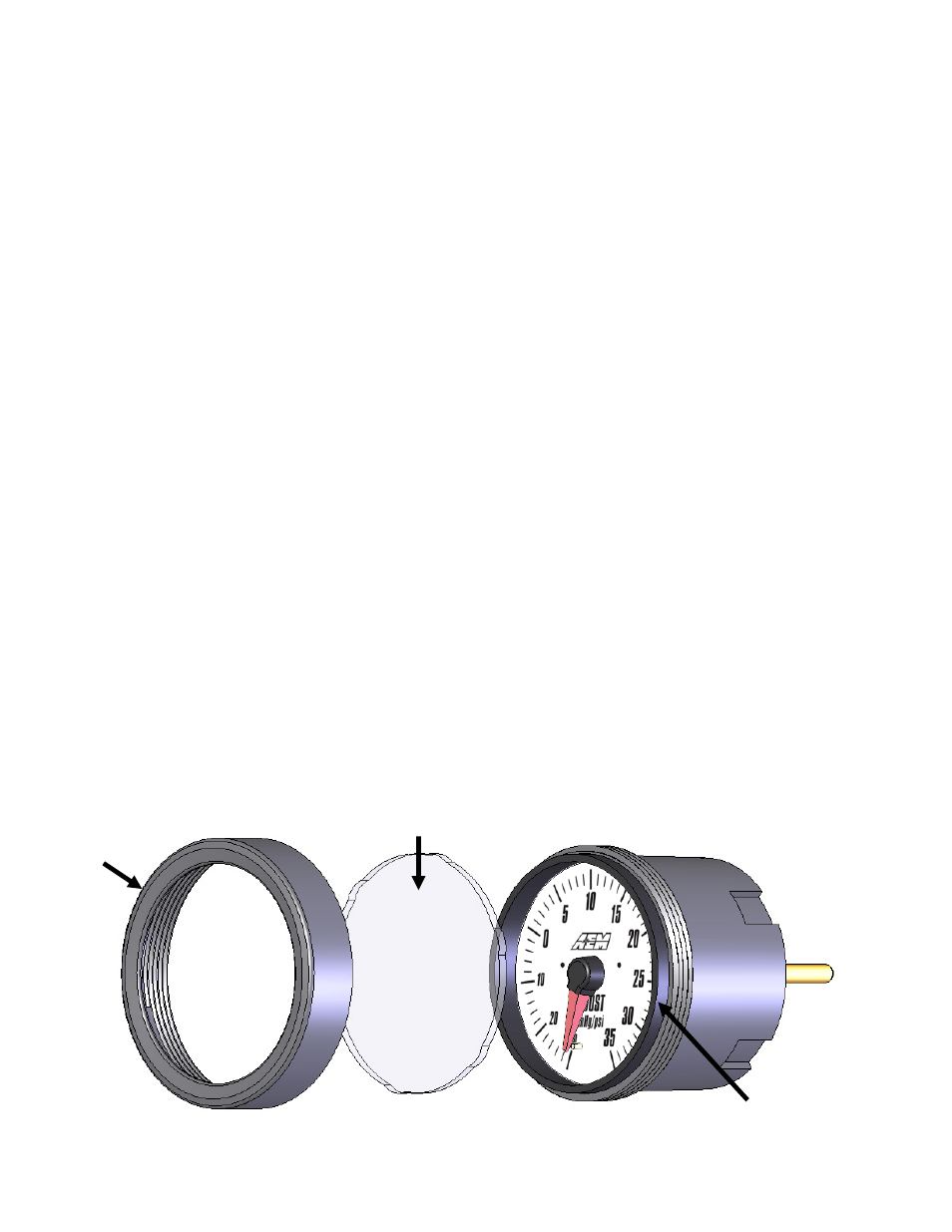
Changing the Bezel
The AEM Boost Gauge comes with the black bezel installed. However, a silver bezel is
also included in the gauge kit. To change the bezel, orient the gauge so you are looking
at the faceplate. Rotate the bezel counter-clockwise to unscrew it from the gauge cup.
The bezel, lens, and rubber spacer are all removable. Reassemble the gauge as
shown below in Figure 3. Note: When reassembling the gauge, it may be necessary to
apply a light amount of pressure on the lens and spacer to keep the faceplate from
rotating when reinstalling the bezel. Do not over tighten the bezel when
reassembling the gauge.
Figure 3. Changing Bezels
BEZEL
LENS
RUBBER
SPACER