AEM 30-4350 Tru-Boost Controller Gauge User Manual
Page 3
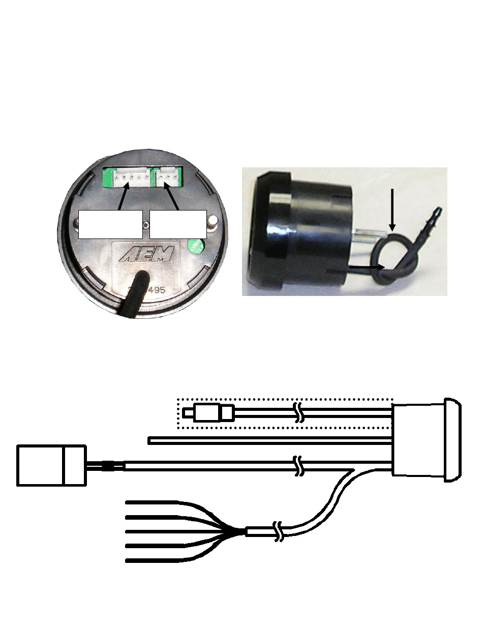
Installing the Gauge
The AEM Tru Boost boost controller gauge requires a standard 2 1/16” (52MM)
ounting hole and can be mounted in a flat panel or most standard gauge pods. The
two wire bundles and a 5-pin connector. The 5-pin connector
connec
t
to
m
included cable contains
ts to a mating 5-pin connector on the back of the gauge. See Figure 2. Connec
the black and red wires in the long 2-wire bundle to the leads from the boost solenoid.
Polarity does not matter. Connect the black wire from the 5-wire bundle to a good
ground. Connect the 2 red wires to a fused, switched, +12Vdc power source. The gray
wire is an optional low side driver output. The orange wire is an optional scramble
boost input. The orange and gray wires do not need to be connected for the gauge
function.
Boost Hose
Page 3
The boost hose protruding from the back
ressure
using the on-board pressure sensor, the boost
ose must be connected to manifold pressure. Connect the boost hose to manifold
re
Figure 2. Connector Locations
of the gauge is connected to the on-board
p
sensor. See Figure 3. When
h
pressure using the supplied tubing and 1/8” NPT barb or an existing manifold pressu
port. (NOTE: Do not pull on the boost hose) See Figure 4 for a connection diagram.
Figure 3. Boost Hose
5-pin
connector
3-pin
connector
OPTIONAL 75 PSIA
SENSOR AND CABLE
B
RED
BOOST
SOLENOID
Tru Boost
RE
D, FUSED +12VDC)
RED (SWITC ED, FUSED +12VDC)
G
MANIFOLD
PRESSURE
LACK
D (SWITCHE
H
BLACK (POWER GROUND)
ORANGE (SCRAMBLE BOOST)
RAY (LOW SIDE OUTPUT)
Figure 4. Connection Diagram