AEM 30-3705 Infinity-6/8h Mini-Harness User Manual
Page 19
16
© 2014 AEM Performance Electronics
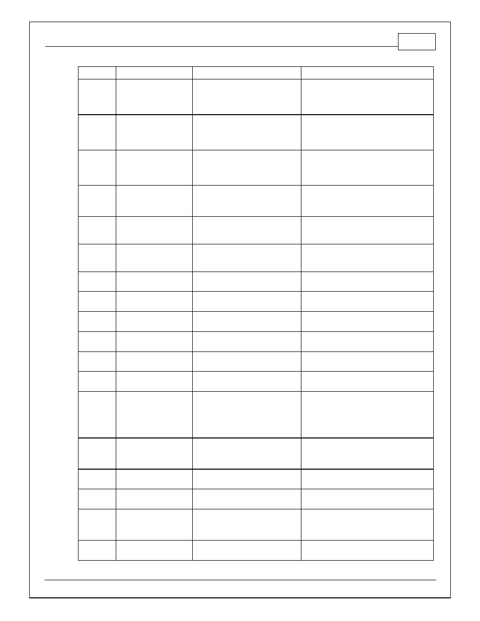
Infinity Pin
Hardware Ref.
Hardware Specification
Notes
C1-31**
Coil 7
(**Infinity-8H Only)
25 mA max source current
Available on P/N 30-7108 only. 0-5V Falling
edge fire. DO NOT connect directly to coil
primary. Must use an ignitor OR CDI that
accepts a FALLING edge fire signal.
C1-32*
Digital_In_7
(*Infinity-6 Only)
10K pullup to 12V. Will work with
ground or floating switches.
Available on P/N 30-7106 only. Input can be
assigned to different pins. See Setup Wizard
page Input Function Assignments for input
mapping options.
C1-32**
Coil 8
(**Infinity-8H Only)
25 mA max source current
Available on P/N 30-7108 only. 0-5V Falling
edge fire. DO NOT connect directly to coil
primary. Must use an ignitor OR CDI that
accepts a FALLING edge fire signal.
C1-33
Power Ground
Power Ground
Connect directly to battery ground
C1-34
CANL_Aout
Dedicated High Speed CAN
Transceiver
Recommend twisted pair (one twist per 2")
with terminating resistor. Contact AEM for
additional information.
C1-35
CANH_Aout
Dedicated High Speed CAN
Transceiver
Recommend twisted pair (one twist per 2")
with terminating resistor. Contact AEM for
additional information.
C1-36
CanL_Bout
Dedicated High Speed CAN
Transceiver
Not used, reserved for future expansion.
C1-37
CanH_Bout
Dedicated High Speed CAN
Transceiver
Not used, reserved for future expansion.
C1-38
Analog_In_Temp_1
12 bit A/D, 2.49K pullup to 5V
See "Coolant Temperature" Setup Wizard for
selection.
C1-39
Analog_In_Temp_2
12 bit A/D, 2.49K pullup to 5V
See "Air Temperature" Setup Wizard for
selection.
C1-40
Analog_In_Temp_3
12 bit A/D, 2.49K pullup to 5V
See 1D table OilTempCal table for calibration
data and OilTemp [C] for channel data.
C1-41
Lowside Fuel Pump drive
Lowside switch, 1.7A max, NO
internal flyback diode.
Switched ground. Will prime for 2 seconds at
key on and activate if RPM > 0.
C1-42
LowsideSwitch_1
Lowside switch, 6A max with internal
flyback diode. Inductive load should
NOT have full time power.
See Setup Wizard page Boost Control for
options. Monitor BoostControl [%] channel for
output state.
C1-43
Power Ground
Power Ground
Connect directly to battery ground
C1-44
Knock Sensor 1
Dedicated knock signal processor
See Setup Wizard page Knock Setup for
options.
C1-45
Knock Sensor 2
Dedicated knock signal processor
See Setup Wizard page Knock Setup for
options.
C1-46
Power Ground
Power Ground
Connect directly to battery ground
C1-47
+12V_Relay_Control
0.7A max ground sink for external
relay control
Will activate at key on and at key off according
to the configuration settings.