Rear panel connections – BNC 835-3 User Manual User Manual
Page 6
Amplitude - The current value for output power. Units: dBm
Range: -70.0 to +25.0 dBm (option PE/PE2: -150.0 to + 25 dBm)
Resolution 0.1 dB
Phase lock – External reference disabled, not locked or locked to integer multiple of 1 MHz
Range: 1 to 100 MHz
LAN – The current IP address of the instrument
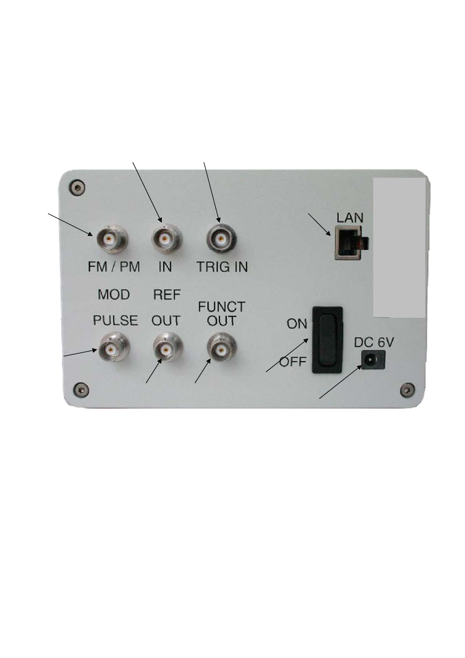
Rear Panel Connections
Figure 2 835-3 Rear Panel View
1 Power switch
The power switch disconnects the signal generator from the DC input
completely, including the internal high-stability reference. After switching on this switch,
the signal generator enters into standby with the OCXO warming up and RF out switched
off. The red power LED (option HC only) on the front panel is turned on.
2 DC IN power receptacle
The power receptacle accepts a two-pin plug from the external
6 V DC power adapter
3 RJ-45 host connector
Used for connecting with a controller, such as a PC or Labtop.
4 FM/PM MOD IN connector
This BNC input connector accepts a 0 to 2 V (peak) signal for
FM modulation. The damage level is 4 Vrms.
5 REF IN connector
Female BNC connector, accepts a TTL or -5 to +15 dBm sine signal
from an external reference oscillator that is within ±1 ppm of the programmed reference
frequency. The nominal input impedance is 50 ohm.
6