Front panel overview (non-hc version), Displayed parameter formats, Main lcd display – BNC 835-3 User Manual User Manual
Page 5
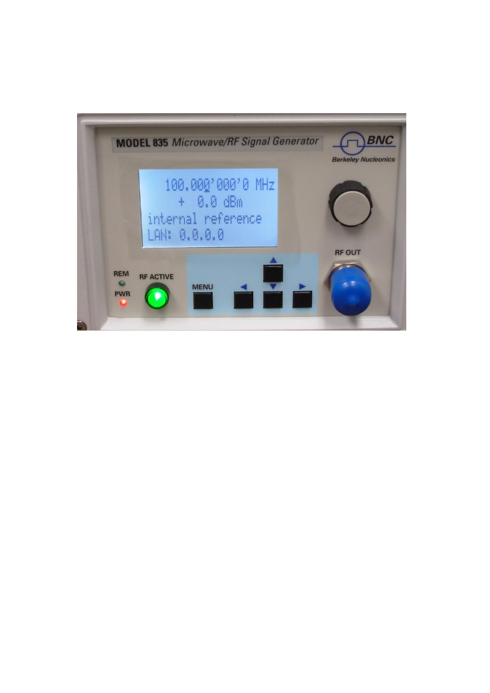
Front Panel Overview (non-HC version)
The front panel contains a status display, a RF output female N-type connector, and a RF
on/off key (Figure 1). The LCD screen shows information on the current function. Information
includes status indicators, frequency and amplitude settings, current connectivity status, and
error messages.
Figure 1 8 3 5 - 3 Front Panel View
RF On/Off button
The ON/OFF key toggles between RF output on and RF output off. The
green light (*) is indicating whether the RF output is enabled (light on) or not.
RF 50Ω connector
This female N- type connector provides the output for RF signals. The
impedance is 50 ohm. The damage level is +30 dBm maximum. The maximum allowed DC
level is +/- 10 V.
Displayed Parameter Formats
Main LCD display
There are two parameters displayed in the main menu: frequency in Hz (1
st
line) and RF
amplitude in dBm (2
nd
line).
On the 3
rd
line the lock status to an external reference source is displayed.
The 4
th
line provides IP address of the controlled source. The display is updated each time a
value is changed.
Frequency - The current value for center frequency. Units: Hz
Range: 9’000 to 3’400’000’000 Hz
Resolution: 0.001 Hz
5