Preparation of bull bar – ARB 3415120 User Manual
Page 14
Last Rev Date: 17 SEPTEMBER 2008
Page 14 of 20
Fitting instructions# 3783312
Copyright © 2005 by ARB Corporation Limited. All rights reserved, this document must not be reproduced without the express authority of ARB Corporation Ltd
PREPARATION OF BULL BAR
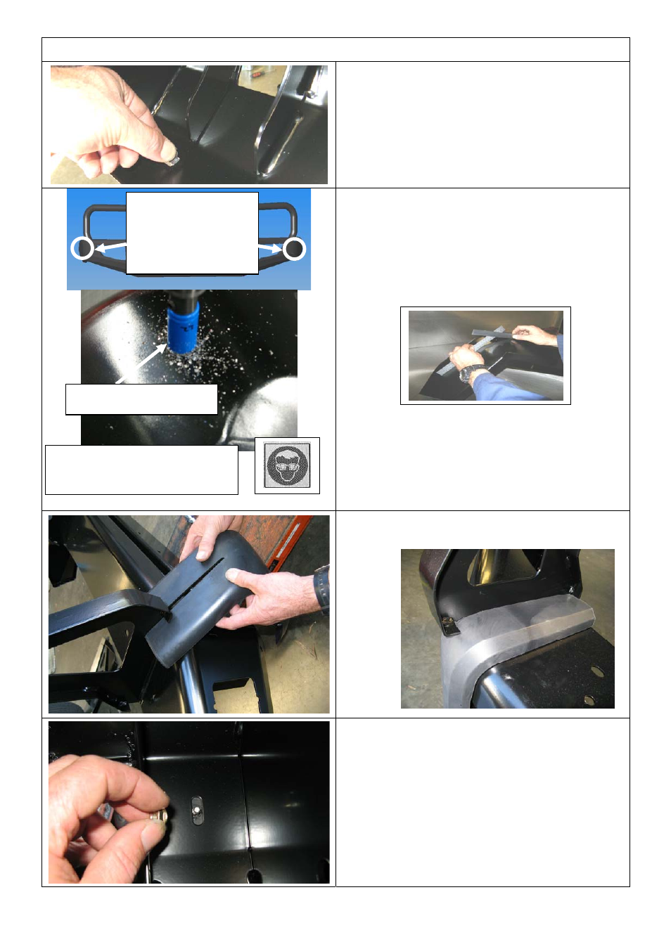
60. Fit 4 x M6 cage nuts to bottom inside
face of lower pan in square holes as
shown.
Hint: A small flat blade screwdriver may help to
press nut cage flanges into hole.
61. If parking sensors are to be fitted, mark
out the hole positions, located in the
middle of the large corner radius of the
wings and 90mm down from the top face.
(Similar position to original bumper)
Hint: Use two rules across flat faces to find
mid point of radius
62. Once Dia 22 (7/8”) hole is drilled and
fully deburred, check that the hole size is
actually Dia 22.0 – 22.8mm, better if on
larger side. Trial fit sleeve and sensor.
63. Once checked use some fast drying
primer paint to seal bare edges.
64. Carefully slide top section of buffer past
edge of cover strap as shown
65. Adjust buffers so they sit neatly on the
bull bar profile then secure using M6
flange nuts over studs.
NOTE: Do not over tighten nuts as damage
to buffer may result.
Warning: Cutting operations
can result in flying debris, safety
glasses should be worn.
Sensors fit on these
outer corners, 90mm
down from top face
in the center of the
corner radius
Hole saw Dia 22.0 (7/8”)