Caution, Warning, Step 6 — provide for condensate disposal – Bryant 604D--A User Manual
Page 9: Step 7 — install electrical connections
9
Step 6 — Provide for Condensate Disposal
NOTE: Ensure that condensate--water disposal methods comply
with local codes, restrictions, and practices.
The 604D----A units dispose of condensate through a 3/4 in. NPT
female fitting that exits on the compressor end of the unit.
Condensate water can be drained directly onto the roof in rooftop
installations (where permitted) or onto a gravel apron in ground
level installations. Install a field--supplied 2--in. (51 mm)
condensate trap at end of condensate connection to ensure proper
drainage. Make sure that the outlet of the trap is at least 1 in. (25
mm) lower than the drain--pan condensate connection to prevent
the pan from overflowing. Prime the trap with water. When using a
gravel apron, make sure it slopes away from the unit.
If the installation requires draining the condensate water away from
the unit, install a field--supplied 2 --in. (51mm) trap at the
condensate connection to ensure proper drainage. Condensate trap
is available as an accessory or is field--supplied. Make sure that the
outlet of the trap is at least 1 in. (25 mm) lower than the unit
drain--pan condensate connection to prevent the pan from
overflowing. Connect a drain trough using a minimum of
field--supplied 3/4--in. PVC or field--supplied 3/4--in. copper pipe
at outlet end of the 2--in. (51 mm) trap. (See Fig. 10) Do not
undersize the tube. Pitch the drain trough downward at a slope of at
least 1 in. (25 mm) every 10 ft (3 m) of horizontal run. Be sure to
check the drain trough for leaks. Prime the trap at the beginning of
the cooling season start--up.
Step 7 — Install Electrical Connections
UNIT COMPONENT DAMAGE HAZARD
Failure to follow this caution may result in damage to the unit
being installed.
1. Make all electrical connections in accordance with NEC
NFPA 70 (latest edition) and local electrical codes
governing such wiring. In Canada, all electrical
connections must be in accordance with CSA standard
C22.1 Canadian Electrical Code Part 1 and applicable
local codes. Refer to unit wiring diagram.
2. Use only copper conductor for connections between
field--supplied electrical disconnect switch and unit. DO
NOT USE ALUMINUM WIRE.
3. Be sure that high--voltage power to unit is within
operating voltage range indicated on unit rating plate. On
3--phase units, ensure phases are balanced within 2
percent. Consult local power company for correction of
improper voltage and/or phase imbalance.
4. Do not damage internal components when drilling
through any panel to mount electrical hardware, conduit,
etc.
!
CAUTION
ELECTRICAL SHOCK HAZARD
Failure to follow this warning could result in personal injury
or death.
The unit cabinet must have an uninterrupted, unbroken
electrical ground. This ground may consist of an electrical
wire connected to the unit ground screw in the control
compartment, or conduit approved for electrical ground when
installed in accordance with NEC,NFPA 70 National Fire
Protection Association (latest edition) (in Canada, Canadian
Electrical Code CSA C22.1) and local electrical codes.
!
WARNING
High--Voltage Connections
The unit must have a separate electrical service with a
field--supplied, waterproof disconnect switch mounted at, or within
sight from the unit. Refer to the unit rating plate, NEC and local
codes for maximum fuse/circuit breaker size and minimum circuit
amps (ampacity) for wire sizing.
The field--supplied disconnect may be mounted on the unit over
the high--voltage inlet hole when the standard power and
low--voltage entry points are used. See Fig. 2 and 3 for acceptable
location. Remove high voltage knockout.
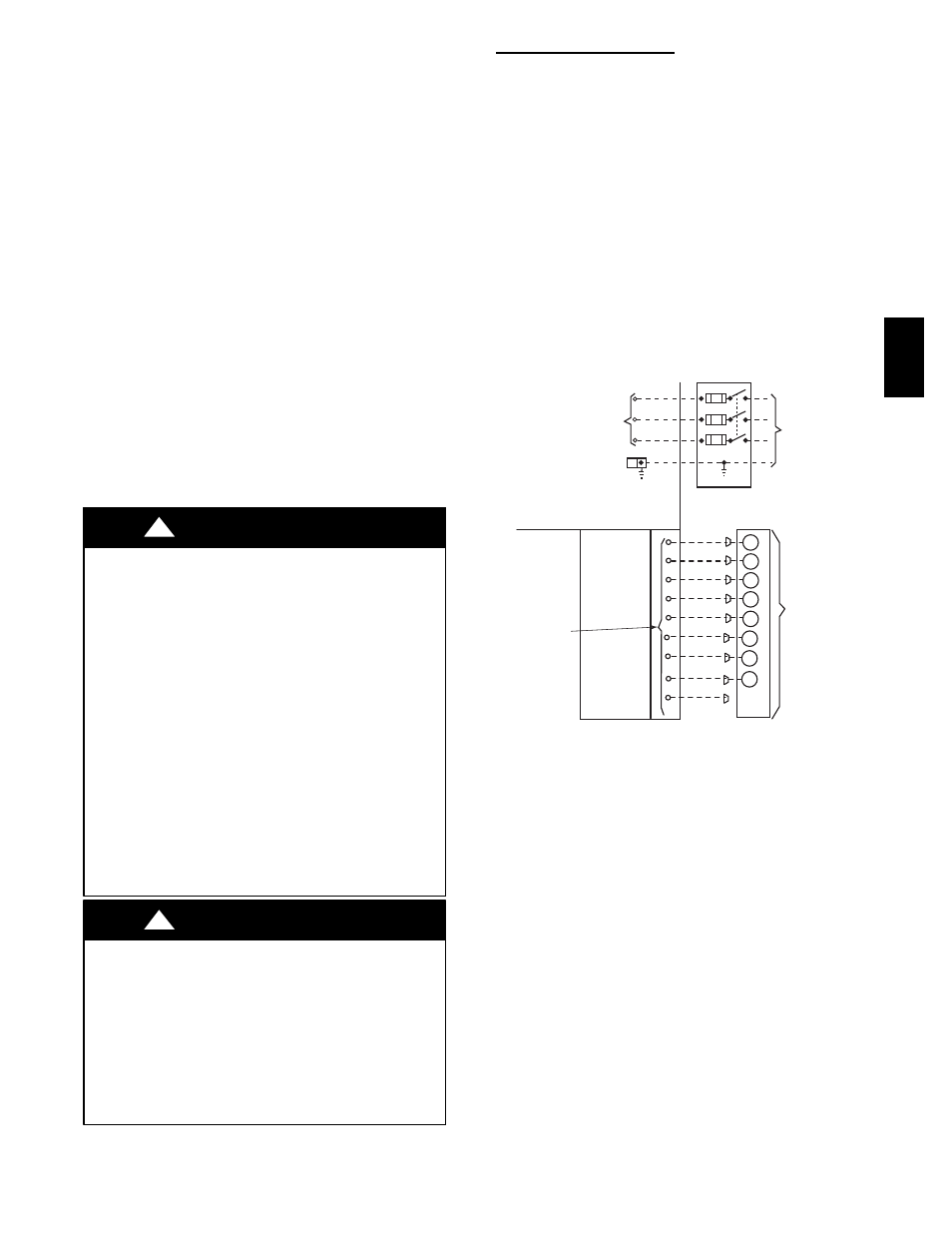
See unit wiring label (Fig. 11--13) and Fig. 9 for reference when
making high voltage connections. Proceed as follows to complete
the high--voltage connections to the unit.
Single phase units:
1. Run the high--voltage (L1, L2) and ground lead into the
control box.
2. Connect ground lead to chassis ground connection.
3. Locate the black and yellow wires connected to the line side
of the contactor.
POWER
SUPPLY
FIELD-SUPPLIED
FUSED DISCONNECT
HIGH VOLTAGE
POWER LEADS
(SEE UNIT WIRING
LABEL)
EQUIP GR
CONTROL BOX
LOW-VOLTAGE
POWER LEADS
(SEE UNIT
WIRING LABEL
)
W1
Y
G
R
C
WHT(W1)
YEL(Y)
GRN(G)
RED(R)
BRN(C)
THERMOSTAT
(TYPICAL)
ORN(O)
3-PHASE SHOWN
1-PHASE USES
TWO POWER
LEADS
W2
VIO (W2)
O
SPLICE BOX
DH
BLU(DH)
3-Phase
Only
GRA(Y2)
A09071
Fig. 9 -- High-- and Control--Voltage Connections
4. Connect field L1 to black wire on connection 11 of the
compressor contactor.
5. Connect field wire L2 to yellow wire on connection 23 of
the compressor contactor.
Three--phase units:
1. Run the high--voltage (L1, L2, L3) and ground lead into the
control box.
2. Connect ground lead to chassis ground connection.
3. Locate the black and yellow wires connected to the line side
of the contactor.
4. Connect field L1 to black wire on connection 11 of the
compressor contactor.
5. Connect field wire L3 to yellow wire on connection 13 of
the compressor contactor.
6. Connect field wire L2 to blue wire from compressor.
604D
--
--
A