Warning, Caution – Bryant 604D--A User Manual
Page 8
8
PERSONAL
INJURY
AND
ELECTRICAL
OPERATION HAZARD
Failure to follow this warning could result in personal
injury or death.
For vertical supply and return units, tools or parts could
drop into ductwork Install a 90 degree turn in the return
ductwork between the unit and the conditioned space. If a
90 degree elbow cannot be installed, then a grille of
sufficient strength and density should be installed to prevent
objects from falling into the conditioned space. Units with
electric heaters require 90 degree elbow in supply duct.
!
WARNING
When designing and installing ductwork, consider the following:
1. All units should have field--supplied filters or accessory
filter rack installed in the return--air side of the unit.
Recommended sizes for filters are shown in Table 1.
2. Avoid abrupt duct size increases and reductions. Abrupt
change in duct size adversely affects air performance.
IMPORTANT: Use flexible connectors between ductwork and
unit to prevent transmission of vibration. Use suitable gaskets to
ensure weather tight and airtight seal. When electric heat is
installed, use fireproof canvas (or similar heat resistant material)
connector between ductwork and unit discharge connection. If
flexible duct is used, insert a sheet metal sleeve inside duct. Heat
resistant duct connector (or sheet metal sleeve) must extend 24--in.
(610 mm) from electric heater element.
3. Size ductwork for cooling air quantity (cfm). The minimum
air quantity for proper electric heater operation is listed in
Table 2. Heater limit switches may trip at air quantities
below those recommended.
4. Seal, insulate, and weatherproof all external ductwork. Seal,
insulate and cover with a vapor barrier all ductwork passing
through conditioned spaces. Follow latest Sheet Metal and
Air Conditioning
Contractors
National Association
(SMACNA) and Air Conditioning Contractors Association
(ACCA) minimum installation standards for residential
heating and air conditioning systems.
5. Secure all ducts to building structure. Flash, weatherproof,
and vibration--isolate duct openings in wall or roof
according to good construction practices.
Converting Horizontal Discharge Units to Downflow
(Vertical) Discharge Units
ELECTRICAL SHOCK HAZARD
Failure to follow this warning could result in personal injury
or death.
Before installing or servicing system, always turn off main
power to system and install lockout tag. There may be more
than one disconnect switch.
!
WARNING
1. Open all electrical disconnects and install lockout tag before
starting any service work.
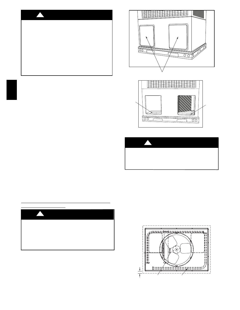
2. Remove horizontal (metal) ductcovers to access vertical
(downflow) discharge duct knockouts in unit basepan. (See
Fig. 7.)
3. After completing unit conversion, perform all safety checks
and power up unit.
Horizontal Duct Covers
A09061
Basepan
Downflow
(Vertical)
Supply
Knockout
Basepan
Downflow
(Vertical)
Return
Knockout
A09088
Fig. 7 --
Supply and Return Duct Openings
PROPERTY DAMAGE HAZARD
Failure to follow this caution may result in property damage.
Collect ALL screws that were removed. DO NOT leave screws
on rooftop as permanent damage to the roof may occur.
!
CAUTION
To remove downflow return and supply knockout covers, break
front and right side connections tabs with a screwdriver and
hammer. Push cover down to break rear and left side tabs.
NOTE: These panels are held in place with tabs similar to an
electrical knockout. Reinstall horizontal duct covers (Fig. 7)
shipped on unit from factory. Insure openings are air and
watertight.
NOTE: The design and installation of the duct system must be in
accordance with the standards of the NFPA for installation of non
residence--type air conditioning and ventilating systems, NFPA
90A or residence--type, NFPA 90B; and/or local codes and
ordinances.
OPTIONAL
RETURN
AIR
OPENING
OPTIONAL
SUPPLY
AIR
OPENING
EVAP. COIL
COND. COIL
2˝
(50.8mm)
A07926
Fig. 8 -- Slab Mounting Detail
604D
--
--
A