Bryant 544B User Manual
Model 544b, Bryant, Split-system heat pump units
Attention! The text in this document has been recognized automatically. To view the original document, you can use the "Original mode".
Bryant
Airconditioning
Indianapolis, IN
City of Industry, CA
SPLIT-SYSTEM
HEAT PUMP UNITS
MODEL 544B
Sizes Q18 thru 060
The 544B Outdoor Sections of split-system heat pumps are
designed for quiet, reliable heating during the winter and cooling
during the summer. These heat pump systems provide economy
of operation through energy conservation. They recover heat for
indoor comfort from outdoor air during the heating season and,
by automaticaliy reversing the refrigerant system, remove indoor
heat and excess humidity during the cooling season. All models
are API certified.
FEATURES
COMPRESSOR—
Designed specifically for heat pump duty, with
high energy efficiency during heating and cooling operation.
Each compressor is hermetically sealed against contamination
to assure long life and dependable performance, internally
sprung and externally mounted on rubber isolators for quiet
operation. Continuous compressor operation is approved down
to -40°F in the heating mode, and down to 55°F in the cooling
mode. (See heating and cooling performance tables.) Ail models
include a discharge-tube muffler to prevent sound transmission
of the compressor pulsations to the indoors or outdoors.
BUILT-IN RELIABILITY COMPONENTS—
Includes a suction-
tube accumulator that keeps liquid refrigerant from reaching the
compressor; a low-pressure switch that stops the compressor if
refrigerant charge is lost; a crankcase heater to keep the com
pressor oil warm and free of refrigerant for maximum lubricity; a
compressor relief valve for high-pressure protection; and com
pressor quick-start components to assure reliable operation of
the
units
during
brownout
conditions
and
low
outdoor
temperatures.
PRINTED-CIRCUIT BOARD
—The board incorporates a defrost
control which contains the defrost relay, defrost timer, and low-
voltage terminal board. The defrost control is a time/temperature
initiation/termination control which includes three field-selecta
ble time periods of 30,50, and 90 minutes.
The printed-circuit board also has a speedup feature that con
verts the defrost cycle time from minutes to seconds to aid in
troubleshooting.
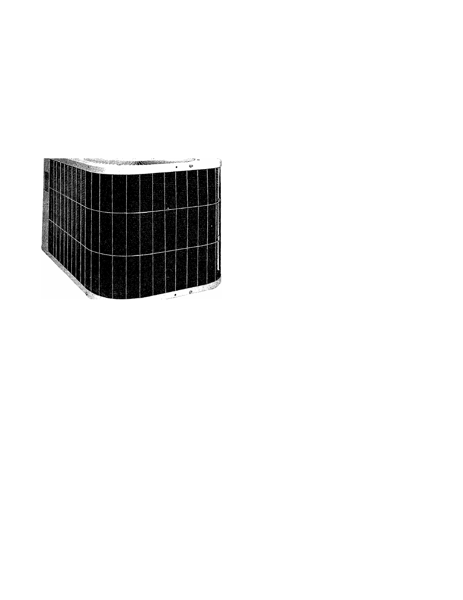
WEATHER-PROTECTIVE CABINET—
The low-profile design of
the 544B units, with the pleasing malibu beige and jade exterior,
blends in well with plants and shrubbery. Galvanized steel,
coated with a layer of zinc phosphate to which a coat of alkyd
melamine enamel is applied and baked on, is used throughout.
This provides a hard, smooth finish that lasts for many years. All
screws in the cabinet exterior are stainless steel for a durable,
rust-resistant, quality appearance.
TIME/TEMPERATURE DEFROST
—The defrost cycle is initiated
by a time/temperature control to clear the coil of frost and ice.
The cycle is started only if the defrost thermostat senses ice
buildup on the outdoor coil. After a few minutes, the control
automatically returns the unit to the heating cycle.
UNIT DESIGN—
All units are equipped with totally enclosed fan
motors for greater reliability under rain and snow conditions.
The large, wraparound coil is designed for optimum heat trans
fer during heating and cooling. The vertical air discharge carries
the sound and air up and away from adjacent patio areas and
foliage. Sufficient space is provided between rows of composite
coils so they can be cleaned with a common garden hose. A
divider panel is installed between the compressor and coil sec
tion so that the unit can be checked and serviced while
operating.
EXTERNAL SERVICE VALVES
—Both brass refrigerant service
valves are externally located so that refrigerant tube connec
tions can be made quickly and easily. Each valve has a service
port for ease of checking operating refrigerant pressures. The
valves are designed for refrigerant tube flare connections.
PDS No. 544B.18 1B