Step 4 — electrical controls and wiring, Step 5 — refrigerant circuit – Bryant 604D--A User Manual
Page 26
26
OF2
OF1
ON
QUIET
SHIFT
120
30
60
60
30
90
INTER
V
AL
TIMER
OFF
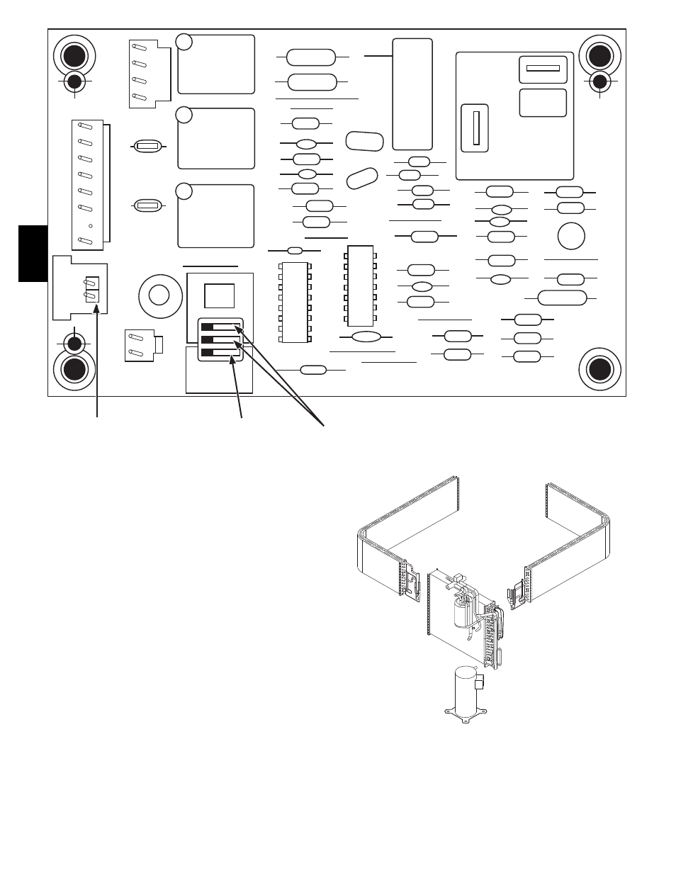
P3
DFT
O R
W
2
Y C
T2 C C O
DFT
T1
Y
P1
J1
SPEEDUP
Speedup
Pins
Defrost interval
DIP switches
Quiet
Shift
A08020
Fig. 18 -- Defrost Control
Step 4 — Electrical Controls and Wiring
Inspect and check the electrical controls and wiring annually. Be
sure to turn off the electrical power to the unit.
Remove access panels (see Fig. 20) to locate all the electrical
controls and wiring. Check all electrical connections for tightness.
Tighten all screw connections. If any discolored or burned
connections are noticed, disassemble the connection, clean all the
parts, restrip the wire end and reassemble the connection properly
and securely.
After inspecting the electrical controls and wiring, replace all the
panels. Start the unit, and observe at least one complete cooling
cycle to ensure proper operation. If discrepancies are observed in
operating cycle, or if a suspected malfunction has occurred, check
each
electrical
component
with
the
proper
electrical
instrumentation. Refer to the unit wiring label when making these
checkouts.
Step 5 — Refrigerant Circuit
Inspect all refrigerant tubing connections and the unit base for oil
accumulation annually. Detecting oil generally indicates a
refrigerant leak.
If oil is detected or if low performance is suspected, leak--test all
refrigerant tubing using an electronic leak detector, or liquid--soap
solution. If a refrigerant leak is detected, refer to Check for
Refrigerant Leaks section.
If no refrigerant leaks are found and low performance is suspected,
refer to Checking and Adjusting Refrigerant Charge section.
C99097
Fig. 19 -- Refrigerant Circuit
604D
--
--
A