Warning, Step 5 — select and install ductwork, Rigging/lifting of unit (see fig. 5.) – Bryant 604D--A User Manual
Page 7: 604d -- -- a
7
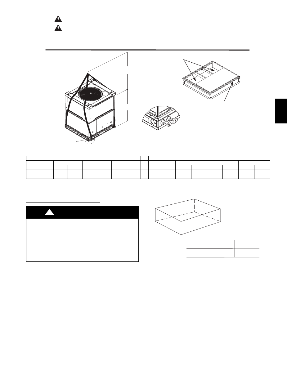
ACCESS PANELS MUST BE IN PLACE WHEN RIGGING.
PANNEAUX D'ACCES DOIT ÊTRE EN PLACE POUR MANIPULATION.
50CY502286 2.0
CAUTION - NOTICE TO RIGGERS
PRUDENCE - AVIS AUX MANIPULATEUR
Use top skid as spreader bar. / Utiliser la palette du haut comme barre de répartition
SEAL STRIP MUST BE IN
PLACE BEFORE PLACING
UNIT ON ROOF CURB
DUCTS
DETAIL A
VOIR DÉTAIL A
MINIMUM HEIGHT: 36" (914.4 mm)
HAUTEUR MINIMUM
UNIT HEIGHT
HAUTEUR D'UNITÉ
SEE DETAIL A
VOIR DÉTAIL A
BANDE SCELLANT DOIT ÊTRE
EN PLACE AVANT DE PLACER
L'UNITÉ SUR LA BASE DE TOIT
A09051
CORNER WEIGHTS (SMALL CABINET)
CORNER WEIGHTS (LARGE CABINET)
Unit
24
30
36
Unit
42
48
60
lb
kg
lb
kg
lb
kg
lb
kg
lb
kg
lb
kg
Rigging
Weight
327
148
340
154
343
156
Rigging
Weight
419
190
429
195
454
206
*For 460 Volt units add 14 lb (6.35 kg) to the rigging weight.
NOTE: See dimensional drawing for corner weights.
Fig. 5 -- Rigging Weights
Rigging/Lifting of Unit (See Fig. 5.)
UNIT FALLING HAZARD
Failure to follow this warning could result in personal injury
or death.
Large base units must be secured to common curb before
allowing full weight of unit to rest on curb. Install screws
through curb into unit base rails while rigging crane is still
supporting unit.
!
WARNING
Lifting holes are provided in base rails as shown in Fig. 2 and 3.
1. Leave top shipping skid on the unit for use as a spreader bar
to prevent the rigging straps from damaging the unit. If the
skid is not available, use a spreader bar of sufficient length to
protect the unit from damage.
2. Attach shackles, clevis pins, and straps to the base rails of the
unit. Be sure materials are rated to hold the weight of the unit.
(See Fig. 5).
3. Attach a clevis of sufficient strength in the middle of the straps.
Adjust the clevis location to ensure unit is lifted level with the
ground.
After the unit is placed on the roof curb or mounting pad, remove the
top skid.
A
B
C
MAXIMUM ALLOWABLE
DIFFERENCE in. (mm)
A-C
1/4
1/4
1/4
(6.35)
(6.35)
(6.35)
A-B
B-C
A07925
Fig. 6 -- Unit Leveling Tolerances
Step 5 — Select and Install Ductwork
The design and installation of the duct system must be in
accordance with the standards of the NFPA for installation of
non--residence type air conditioning and ventilating systems,
NFPA 90A or residence--type, NFPA 90B and/or local codes and
ordinances.
Select and size ductwork, supply--air registers, and return air grilles
according to ASHRAE (American Society of Heating,
Refrigeration, and Air Conditioning Engineers) recommendations.
The unit has duct flanges on the supply-- and return--air openings
on the side of the unit.
604D
--
--
A