Brady 200M User Manual
Page 47
Bank 1
(For Serial-Interface Printers Only)
The M-Series Printer, with the RS-232 Serial Interface, uses eight
miniature switches located on the rear of the printer, above the
Signal Interface Cable Connector. The ON/OFF positions of these
switches establish some of the Printer Configuration Parameters.
Bank 1 switches must be
properly positioned to
establish serial data
communications with the host
computer. Thereafter, the
position of these switches
should not be changed.
Note: Parallel-interface
printers do not require
these configuration
parameters, therefore
they have no Bank 1
switches.
If these switches are in the
proper position to match the
communication configuration
of the host computer, and the
printer is not receiving data,
refer to the Interconnections
Section and make sure the
correct interface cable is
being used.
Note: The printer is fixed at
1 stop bit, so make sure
that your host device is
also set at 1 stop bit.
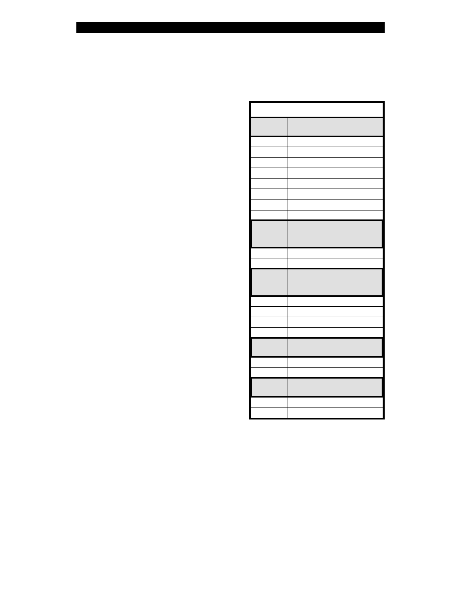
Bank 1
(Serial-Interface Printers Only)
Switch
3 2 1
Baud Rate
R R R
9600 baud
R R L
19200 baud
R L R
110 baud
R L L
300 baud
L R R
600 baud
L R L
1200 baud
L L R
2400 baud
L L L
4800 baud
Switch
4
Data Bits
(
Must be set to 8 Data Bits
to use Code Page 850.)
R
7 Data bits
L
8 Data bits
Switch
6 5
Parity
(If you choose 7 data bits, you must
choose either even or odd parity.)
R R
Even parity
R L
Parity disabled
L R
Odd parity
L L
Parity disabled
Switch
7
Communication
Handshake Control
R
XON/XOFF control
L
DTR/DSR control
Switch
8
Error Detection Protocol
R
No error detection
L
Error detection active
Table 4.1
Configuration and Calibration
M-Series User s Guide
4-2