Bryant Series B 345MAV User Manual
Page 37
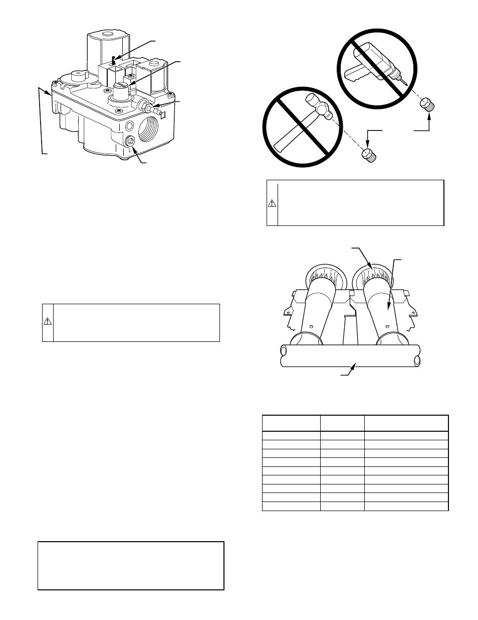
b. Remove cap that conceals adjustment screw for gas
valve regulator. (See Fig. 40.)
c. Turn adjusting screw, counterclockwise (out) to decrease
manifold pressure or clockwise (in) to increase manifold
pressure.
NOTE:
This furnace has been approved for a manifold pressure
of 3.2 in. wc to 3.8 in. wc when installed at altitudes up to 2000 ft.
For altitudes above 2000 ft, the manifold pressure can be adjusted
from 2.0 in. wc to 3.8 in. wc.
CAUTION:
DO NOT bottom out gas valve regulator
adjusting screw. This can result in unregulated manifold
pressure and result in excess overfire and heat exchanger
failures.
NOTE:
If orifice hole appears damaged or it is suspected to have
been redrilled, check orifice hole with a numbered drill bit of
correct size. Never redrill an orifice. A burr-free and squarely
aligned orifice hole is essential for proper flame characteristics.
d. Replace gas valve regulator adjustment screw cap.
e. Replace burner enclosure front and verify adjusted gas
input rate using method outlined in item 3.
f. Look through sight glass in burner enclosure and check
burner flame. Burner flame should be clear blue, almost
transparent. (See Fig. 41.)
3. Verify natural gas input rate by clocking gas meter.
NOTE:
Be sure all pressure tubing, combustion-air and vent
pipes, and burner enclosure front are in place when checking input
by clocking gas meter.
NOTE:
High-Altitude Adjustment
UNITED STATES
At altitudes above 2000 ft, this furnace has been approved for a 2%
derate for each 1000 ft above sea level. See Table 8 for derate
multiplier factor.
EXAMPLE:
100,000 Btuh input furnace installed at 4300 ft.
Furnace Input Rate
at Sea Level
X
Derate
Multiplier
Factor
=
Furnace Input Rate
at Installation
Altitude
100,000
X
0.91
=
91,000
CANADA
At installation altitudes from 2000 to 4500 ft, this furnace must be
derated 5% by an authorized Gas Conversion Station. To deter-
mine correct input rate for altitude, see example above and use
0.95 as derate multiplier factor.
a. Turn off all other gas appliances and pilots.
b. Start furnace and let operate for 3 minutes.
Fig. 40—Redundant Automatic Gas Valve
A95622
MANIFOLD
PRESSURE TAP
GAS
PRESSURE
REGULATOR
ADJUSTMENT
BURNER
ENCLOSURE
REFERENCE
PRESSURE
TAP
INLET
PRESSURE TAP
ON AND
OFF SWITCH
CAUTION:
DO NOT redrill orifices. Improper drilling
(burrs, out-of-round holes, etc.) can cause excessive
burner noise and misdirection of burner flames. This can
result in flame impingement of burners and heat exchang-
ers causing failures.
A93059
BURNER
ORIFICE
Fig. 41—Burner Flame
A89020
BURNER FLAME
BURNER
MANIFOLD
TABLE 8—ALTITUDE DERATE MULTIPLIER FOR U.S.A.
ALTITUDE
(FT)
% OF
DERATE
DERATE MULTIPLIER
FACTOR FOR U.S.A*
0—2000
0
1.00
2001—3000
4—6
0.95
3001—4000
6—8
0.93
4001—5000
8—10
0.91
5001—6000
10—12
0.89
6001—7000
12—14
0.87
7001—8000
14—16
0.85
8001—9000
16—18
0.83
9001—10,000
18—20
0.81
* Derate multiplier factor is based on midpoint altitude for altitude range.
—37—
→