Bryant Gas 340MAV User Manual
Page 29
b. Reposition elastometric (rubber) inducer housing outlet
cap and clamp to appropriate unused inducer housing
connection. Tighten clamp.
WARNING:
Inducer housing outlet cap must be in-
stalled and fully seated against inducer housing. Clamp
must be tightened to prevent any condensate leakage.
Failure to follow this warning could result in electrical
shock, fire, personal injury, or death.
c. Install pipe support (factory-supplied in loose parts bag)
into selected furnace casing vent pipe hole. Pipe support
should be positioned at bottom of casing hole.
WARNING:
Vent pipe must be installed and fully
seated against inducer housing internal stop. Clamp must
be tightened to prevent any condensate leakage. Failure to
follow this warning could result in electrical shock, fire,
personal injury, or death.
NOTE:
A 2-in. diameter pipe must be used within the furnace
casing. Make all pipe diameter transitions outside furnace casing.
d. Be certain that mating surfaces of inducer housing
connection, elastomeric coupling, and 2-in. diameter
vent pipe are clean and dry. Assemble the elastomeric
(rubber) vent coupling (with 2 loose clamps) onto
inducer housing connection. Insert the 2-in. diameter
vent pipe through the elastomeric (rubber) coupling and
TABLE 7—MAXIMUM ALLOWABLE PIPE LENGTH (FT) (CONTINUED)
ALTITUDE (FT)
UNIT SIZE
TERMINATION
TYPE
PIPE DIA
(IN.)*
NUMBER OF 90° ELBOWS
1
2
3
4
5
6
8001 to 9000‡
024040
036040
2 Pipe or 2-in
Concentric
1-1/2
46
41
36
31
29
24
2
62
60
58
56
55
53
024060
036060
048060
2 Pipe or 2-in
Concentric
1-1/2
11
6
NA
NA
NA
NA
2
49
44
42
37
35
34
036080
048080
060080
2 Pipe or 2-in
Concentric
2
33
28
17
12
10
NA
2-1/2
62
60
58
56
55
53
048100
060100
2 Pipe or 3-in
Concentric
2-1/2
23
15
7
5
NA
NA
3
59
54
49
44
39
34
060120
2 Pipe or 3-in.
Concentric
3† no disk
10
NA
NA
NA
NA
NA
4† no disk
35
30
25
20
15
10
060140
NA
ALTITUDE (FT)
UNIT SIZE
TERMINATION
TYPE
PIPE DIA
(IN.)*
NUMBER OF 90° ELBOWS
1
2
3
4
5
6
9001 to 10,000‡
024040
036040
2 Pipe or 2-in
Concentric
1-1/2
42
37
32
27
25
20
2
57
55
53
51
49
47
024060
036060
048060
2 Pipe or 2-in
Concentric
2
45
40
38
33
31
29
036080
048080
060080
2 Pipe or 2-in
Concentric
2
30
25
14
9
7
NA
2-1/2
57
55
53
51
49
47
048100
060100
2 Pipe or 3-in
Concentric
2-1/2
21
13
5
NA
NA
NA
3
54
49
44
39
34
29
060120
2 Pipe or 3-in.
Concentric
4† no disk
10
5
NA
NA
NA
NA
060140
NA
Disk usage-Unless otherwise specified, use perforated disk assembly (factory-supplied in loose parts bag). If one disk is stated, separate 2 halves of perforated disk
assembly and use shouldered disk half. When using shouldered disk half, install screen side toward inlet box.
†Wide radius elbow.
‡Vent sizing for Canadian installations over 4500 ft (1370 m) above sea level are subject to acceptance by the local authorities having jurisdiction.
NA-Not Allowed; pressure switch will not make.
NOTES:
1. Do not use pipe size greater than those specified in table or incomplete combustion, flame disturbance, or flame sense lockout may occur.
2. Size both the combustion-air and vent pipe independently, then use the larger diameter for both pipes.
3. Assume two 45° elbows equal one 90° elbow. Long radius elbows are desirable and may be required in some cases.
4. Elbows and pipe sections within the furnace casing and at the vent termination should not be included in vent length or elbow count.
5. The minimum pipe length is 5 ft for all applications.
6. Use 3-in. diameter vent termination kit for installations requiring 4-in diameter pipe.
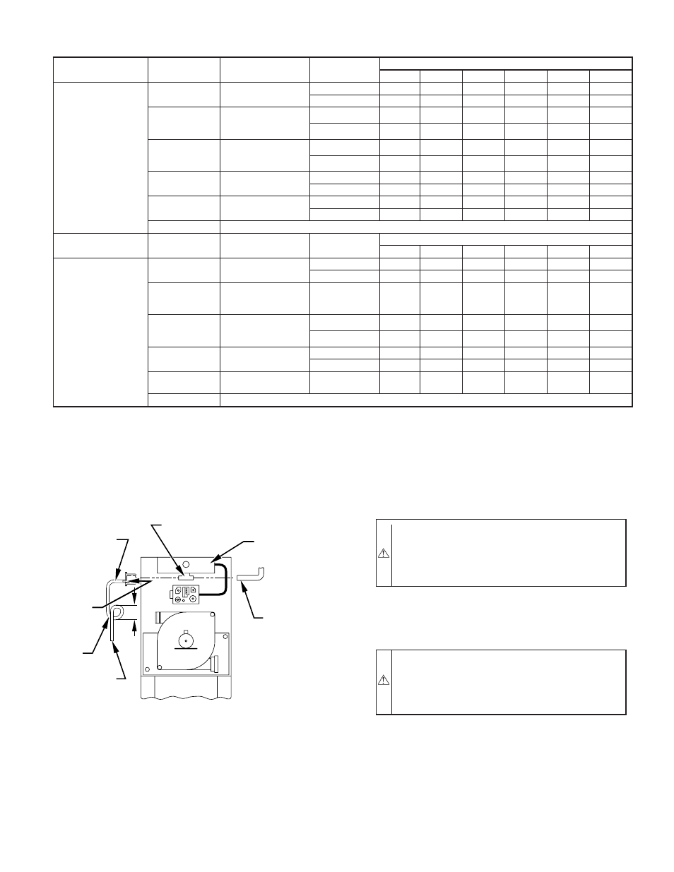
Fig. 35—Air Intake Housing Plug Fitting Drain
A93035
COMBUSTION –
AIR PIPE
BURNER
BOX
COMBUSTION – AIR
INTAKE HOUSING
3/8" ID TUBE
TRAP
TO OPEN
DRAIN
3/16"
DRILL
4
″
MIN
—29—