Dimensions, Ad f e, 313aa v/ ja v – Bryant 313AAV/JAV User Manual
Page 9
9
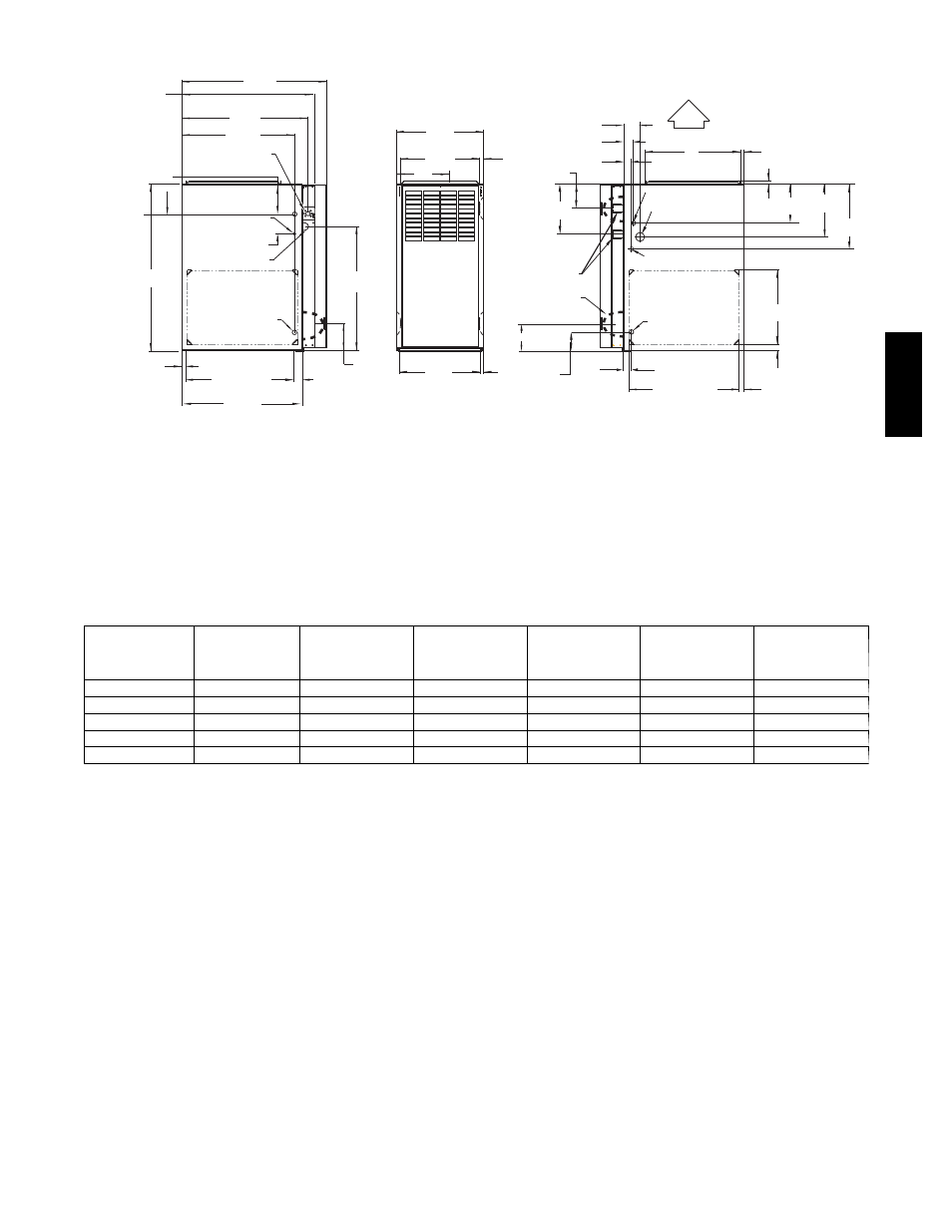
DIMENSIONS
2-7/16"
1-1/8"
28-7/8"
(733mm)
25-1/4"
22-9/16"
JUNCTION BOX
LOCATION
7/8" DI A
ACCESSORY
1/2" (13 mm) DIA.
THERMOSTAT WIRE ENTRY
3-15/16" (84mm)
LEFT HAND GAS
ENTRY
33-5/16"
24-7/8"
5-1/2"
7/8" (22mm) DIA.
ACCESSORY
11/16"
21-5/8"
BOTTOM INLE T
1-11/16"
13/16"
11/16"
4-13/16"
AIRFLOW
19"
OUTLE T
13/16"
11/16"
8-9/16"
VENT OUTLE T
5 PLACES (TYP)
3-3/4"
1-3/4" DIA.RIGHT HAND
GAS ENTRY
7/8" DIA. K.O. WIRE ENTRY
SIDE INLE T
14-7/8"
7/8" DIA. ACCESSORY
1-1/4"
1"
22-1/16"
A
D
F
E
(FLUE COLLAR)
5-15/16"
(135mm)
24"
CASING
1-5/16"
1/2" DIA. K.O.THERMOSTAT
WIRE ENTRY
ALTERNAT E
JUNCTION BOX
LOCATIONS (TYP)
26-1/8"
1-1/2"
7-3/4"
9-5/8"
11-1/2"
5-1/2"
(664mm)
(641mm)
(573mm)
(22mm)
(846mm)
(17mm)
(549mm)
(610mm)
(43mm)
(140mm)
(632mm)
(17mm)
(140mm)
(95mm)
(21mm)
(122mm)
(217mm)
(62mm)
(33mm)
(29mm)
(483mm)
(13mm)
(44mm)
(22mm)
(22mm)
(38mm)
(560mm)
(25mm)
(32mm)
(378mm)
(17mm) (197mm)
(244mm)
(292mm)
(21mm)
A04037
1. Two additional 7/8--in. (22 mm) dia. knockouts are located in the top plate.
2. Minimum return--air openings at furnace, based on metal duct. If flex duct is used, see flex duct manufacturer’s recommendations for equivalent diameters.
3. Minimum return--air opening at furnace.
a. For 800 CFM--16--in. (406 mm) round or 14--1/2 x 12--in. (368 x 305 mm) rectangle.
b. For 1200 CFM--20--in. (508 mm) round or 14--1/2 x 19--1/3 in. (368 x 491 mm)rectangle.
c. For 1600 CFM--22--in. (559 mm) round or 14--1/2 x 22--1/16--in. (368 x 560 mm) rectangle.
d. For airflow requirements above 1800 CFM, see Air Delivery table in Product Data literature for specific use of single side inlets. The use of both side inlets, a
combination of 1 side and the bottom, or the bottom of single side inlets. The use of both side inlets, a combination of one side and the bottom, or the bottom only
will ensure adequate return air openings for airflow requirements above 1800 CFM.
313AAV/JAV
UNIT SIZE
A
CABINET
WIDTH
IN (MM)
D
SUPPLY WIDTH
IN (MM)
E
BOTTOM
RETURN WIDTH
IN (MM)
F
TOP VENT
OUTLET
IN (MM)
VENT
CONNECTION
SIZE
(see Notes 1 & 2)
MEDIA CABINET
SIZE
IN (MM)
024045
14---3/16 (360)
12---9/16 (319)
12---11/16 (322)
9---5/16 (237)
4
16 (406)
048070
17---1/2 (445)
15---7/8 (403)
16---1/8 (410)
11---9/16 (294)
4
16 (406)
048090
21 (533)
19---3/8 (492)
19---1/2 (495)
13---5/16 (338)
4
20 (508)
060110
21 (533)
19---3/8 (492)
19---1/2 (495)
13---5/16 (338)
4
20 (508)
060135
24---1/2 (622)
22---7/8 (581)
23 (584)
15---1/16 (383)
4 (Note 1)
24 (610)
1. 135 size furnaces require 5---in. (127 mm) vents. Use a 4---5 in. (102---127 mm) vent adaptor between furnace and vent stack.
2. See installation instructions for complete installation requirements.
313AA
V/
JA
V