Bryant LOW-BOY 367AAN User Manual
Page 6
OIL CONNECTIONS
Complete instructions for installing fuel oil piping can be found in
oil burner Installation Instructions included with furnace.
Oil line entry holes are provided in side panels. Two holes are
provided in each location so that a 2-pipe system may be used if
desired.
An oil filter should be used with all oil burners and should be
installed as close to burner as possible.
BAROMETRIC DRAFT CONTROL
The barometric draft control shipped with furnace MUST be used
with furnace to ensure proper operation. Instructions for installing
control are packed with control.
ELECTRICAL CONNECTIONS
WARNING:
The unit cabinet must have an uninter-
rupted or unbroken electrical ground to minimize per-
sonal injury if an electrical fault should occur. A green
ground screw is provided in control box for this connec-
tion.
I.
115-V WIRING
Before proceeding with electrical connections, make certain that
voltage, frequency, and phase correspond to that specified on unit
rating plate. Also, check to be sure that service provided by utility
is sufficient to handle load imposed by this equipment. Refer to
rating plate or Table 2 for equipment electrical specifications.
Make all electrical connections in accordance with National
Electrical Code (NEC) ANSI/NFPA 70-1996 and any local codes
or ordinances that might apply. For Canadian installations, all
electrical connections must be made in accordance with Canadian
Electrical Code CSA C22.1 or subauthorities having jurisdiction.
CAUTION:
Do not connect aluminum wire between
disconnect switch and furnace. Use only copper wire.
The control system depends on correct polarity of power supply.
Connect HOT wire (H) and NEUTRAL wire (N) as shown in Fig.
3 or Fig. 4.
A separate line voltage supply MUST be used with a fused
disconnect switch or circuit breaker between main power panel
and unit. (See Fig. 3 or Fig. 4.)
Metallic conduit (where required/used) may terminate at side panel
of unit. It is not necessary to extend conduit inside unit from side
panel to control box.
When replacing any original furnace wiring, use only 105°C No.
14 AWG copper wire.
II.
24-V WIRING
Instructions for wiring thermostat (field supplied) are packed in
thermostat box. Make thermostat connections as shown in Fig. 3 or
Fig. 4 at 24-v terminal board on primary relay.
III.
ACCESSORIES
When installing optional accessories to this appliance, follow
manufacturer’s Installation Instructions included with accessory.
Other than wiring for thermostat, wire with a minimum of type "T"
insulation (63°F rise) must be used for accessories.
FILTERS
WARNING:
Never operate unit without a filter or with
filter access door removed. Failure to adhere to this
warning could lead to a hazardous condition which could
lead to equipment damage and bodily harm.
An internal filter rack is provided as standard equipment with
furnace and is located in blower compartment. A sufficient
clearance should be provided for air filter access. Refer to Table 3
for filter rack flange dimensions for return air duct.
START-UP, ADJUSTMENT, AND SAFETY CHECKOUT
I.
OPERATIONAL CHECKOUT
WARNING:
DO NOT TAMPER WITH UNIT OR
CONTROLS—CALL YOUR SERVICE TECHNICIAN.
Installation of furnace is now complete. Run through the following
checkout and ensure each item has been performed.
1. Correct nozzle size has been selected for desired input rate.
2. Blower wheel support is removed.
3. Electrical wiring is completed according to Fig. 3 or Fig. 4.
4. Blower access door is secured in place.
5. Valve on oil supply line is open.
6. RESET BUTTON on primary control is pushed down.
7. Flame observation door and 2 cleanout access doors located
at front of unit are closed.
8. Thermostat is set for heating mode and set above room
temperature.
If all of the above items have been performed, set main electrical
switch to ON position and burner should start. When burner starts,
proceed to Combustion Check section.
II.
COMBUSTION CHECK
In order to obtain optimum performance from oil burner, the
following setup procedures must be followed:
1. A test kit to measure smoke, stack draft, over-fire draft,
CO
2
, and stack temperatures MUST be used in order to
obtain proper air band setting. Although all of the above
measurements are required for optimum setup and effi-
ciency data, the most important readings that must be taken
are smoke number, over-fire draft, and stack draft.
2. The proper smoke number has been established by engi-
neering tests to be between 0 and 1. This degree of smoke
emission is commonly referred to as a "trace" of smoke. It
is recommended to use a Bacharach true spot smoke test set
or equivalent.
→
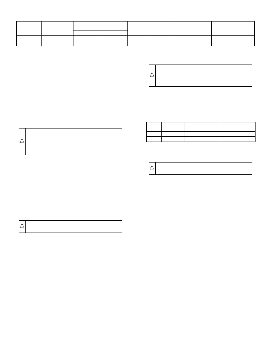
TABLE 2—ELECTRICAL DATA
UNIT
SIZE
VOLTS—
HERTZ—
PHASE
OPERATING
VOLTAGE RANGE
MAX
UNIT
AMPS
MIN
WIRE
GAGE
MAX WIRE
LENGTH (FT)†
MAX FUSE OR
CKT BKR AMPS‡
Max*
Min*
036105
115—60—1
132
104
12.2
14
26
15
060120
115—60—1
132
104
15.7
14
26
20
* Permissible limits of voltage range at which unit will operate satisfactorily.
† Length shown is as measured 1 way along wire path between unit and service panel for maximum 2 percent voltage drop.
‡ Time-delay fuse is recommended.
→
TABLE 3—FILTER SIZE (IN.) AND QUANTITY
UNIT
SIZE
AIR FILTER
SIZE
RETURN OPENING
SIZE
SUPPLY OPENING
SIZE
036105
(2) 12 X 20
20 X 20
20 X 20
060120
(2) 16 X 20
22 X 20
24 X 20
—6—
→
→
→
→