Bryant LOW-BOY 367AAN User Manual
Page 10
IV.
LIMIT CONTROL CHECK
After furnace has been in operation for at least 15 minutes, restrict
return-air supply by blocking filters or closing return registers and
allow furnace to shut down on high limit. The burner should shut
off, and main blower should continue to run.
Remove restriction, and burner should come back on in a few
minutes.
V.
FOR YEAR-ROUND AIR CONDITIONING
This furnace is designed for use in conjunction with cooling
equipment to provide year-round air conditioning. The blower has
been sized for both heating and cooling, however, fan motor speed
may need to be changed to obtain necessary cooling airflow.
VI.
HEATING
The blower speed is factory set to deliver required airflow at
normal duct static pressure.
VII.
COOLING
The blower speed may be field adjusted to deliver required airflow
for cooling application. (See Table 7.)
VIII.
CONSTANT BLOWER SWITCH
This furnace is equipped with a constant low-speed blower option.
Whenever room thermostat is not calling for heating or cooling,
blower runs on low speed in order to provide air circulation. If
constant blower option is not desired, the rocker switch on top of
cabinet may be used to turn off constant speed.
MAINTENANCE
WARNING:
The ability to properly perform mainte-
nance on this equipment requires certain expertise, me-
chanical skills, tools, and equipment. If you do not
possess these, do not attempt to perform any maintenance
on this equipment other than those procedures recom-
mended in the User’s Manual. FAILURE TO FOLLOW
THIS WARNING COULD RESULT IN POSSIBLE
DAMAGE TO THIS EQUIPMENT, SERIOUS PER-
SONAL INJURY, OR DEATH.
WARNING:
Before performing any service functions,
unless operations specifically require power to be on,
make sure all utilities are turned off upstream of appli-
ance. Failure to comply with this warning will cause a fire
hazard and/or bodily harm.
WARNING:
To avoid personal injury, make sure elec-
trical supply power is off before servicing. Failure to
follow this warning could lead to electrical shock, fire, or
death.
I.
GENERAL
In order to keep this furnace in good operating condition and to
maintain its warranty, the furnace MUST be serviced on an annual
basis. This servicing includes a nozzle change, a burner inspection,
a visual check of tube passages through flue outlet and cleanout
ports, and a visual inspection of combustion chamber when burner
is removed.
Depending on above inspection, service could also include a
cleaning and vacuuming of heat exchanger tubes and possibly the
heat exchanger drum section.
Removal of any heat exchanger components which are sealed by
gaskets requires replacement of gasket.
WARNING:
Failure to replace any heat exchanger gas-
kets with new gaskets when any heat exchanger plates or
covers are removed could lead to heat exchanger leakage,
sooting, and/or a hazardous condition capable of causing
bodily harm.
This furnace should never be operated without an air filter.
Disposable filters should be replaced at least once a year. If
equipped to provide cooling, filters should be replaced a minimum
of twice a year. Permanent filters should be cleaned at least twice
a year.
ALWAYS KEEP MAIN OIL VALVE TURNED OFF IF
BURNER IS SHUT DOWN FOR AN EXTENDED PERIOD OF
TIME.
II.
OIL BURNER
For optimum performance, oil burner nozzle should be replaced
once a year. Contact your service technician if you are unsure of
this procedure.
The procedure for nozzle installation and/or replacement is out-
lined in oil burner instruction manual which came with furnace.
After replacement of nozzle, burner should be adjusted in accor-
dance with Combustion Check section of this instruction.
III.
HEAT EXCHANGER AND FLUE PIPE
Ordinarily, it is not necessary to clean heat exchanger or flue pipe
every year, but it is necessary to have your service technician
check unit before each heating season to determine whether
cleaning or replacement of parts is required.
If cleaning is necessary, the following steps should be performed:
→
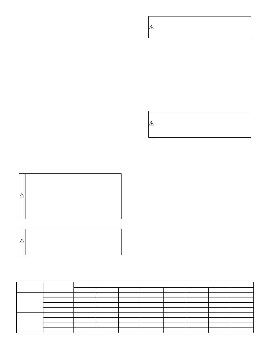
TABLE 7—AIRFLOW DATA (CFM)
UNIT
SIZE
BLOWER
SPEED
EXTERNAL STATIC PRESSURE IN. WC
0.2
0.3
0.4
0.5
0.6
0.7
0.8
0.9
036105
High
1425
1350
1305
1250
1170
1030
925
805
Med-High
1130
1045
1000
950
885
820
745
670
Med-Low
840
810
770
740
685
635
580
500
Low
725
730
740
745
730
715
690
665
060120
High
2080
2041
1965
1864
1702
1576
1474
1336
Med-High
1892
1859
1770
1675
1550
1449
1330
1217
Med-Low
1556
1475
1394
1318
1211
1134
1051
938
Low
1221
1164
1081
998
926
855
782
653
NOTES: 1. Airflow values in cubic ft per minute (CFM) rounded to nearest 5 CFM.
2. Data taken with filters in place.
—10—